Chrysler Sebring, Stratus sedan, Sebring Convertible. Manual - part 344


  Index      Chrysler     Chrysler Sebring, Stratus sedan, Sebring Convertible - service repair manual 2001-2007 year


Search            


Content   ..  342  343  344  345   ..


Chrysler Sebring, Stratus sedan, Sebring Convertible. Manual - part 344


Diagnostic Procedures Information. The scan tool can
provide confirmation that the Programmable Com-
munications Interface (PCI) data bus is functional,
that all of the electronic modules are sending and
receiving the proper messages on the PCI data bus,
and that the power top motor is being sent the
proper hard wired output by the Body Control Mod-
ule (BCM). Refer to the appropriate diagnostic
information and address any Diagnostic Trou-
ble Codes (DTCs) stored in the BCM.

If the problem being diagnosed is an inoperative

power top switch illumination lamp, but the power
top switch operates as designed, replace the power
top switch, (Refer to 8 - ELECTRICAL/POWER TOP/
SWITCH - REMOVAL). If the problem being diag-
nosed is an inoperative power top up or down
perform the following:

(1) Disconnect and isolate the battery negative

cable.

(2) Remove the power top switch, (Refer to 8 -

ELECTRICAL/POWER TOP/SWITCH - REMOVAL).

(3) Disconnect the power top switch wire harness

connector.

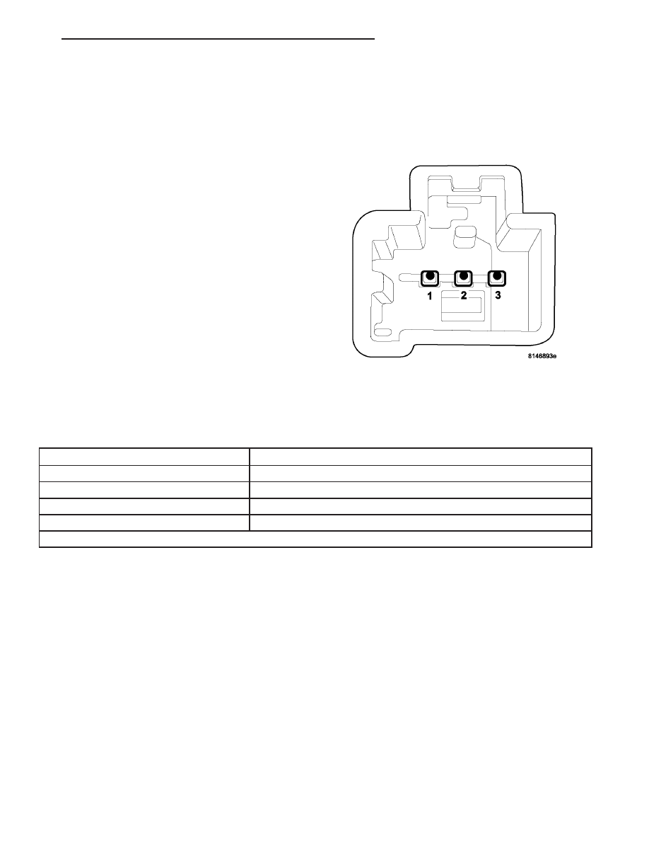
(4) Using an ohmmeter, test the resistances of the

power top switch in each switch position. Refer to,
(Fig. 4) and the POWER TOP SWITCH TEST

CHART. If OK, use a scan tool and the proper Diag-
nostic Procedures Information to complete diagnosis
of the power top system. If not OK, replace the inop-
erative power top switch, (Refer to 8 - ELECTRICAL/
POWER TOP/SWITCH - REMOVAL).

POWER TOP SWITCH TEST CHART

SWITCH POSITION

RESISTANCE BETWEEN PINS 2 and 3

OFF

4.75 K ohms

TOP UP

596 ohms

TOP DOWN

338 ohms

EXPRESS DOWN

175 ohms

ALL RESISTANCE VALUES ARE ± FIVE PERCENT

Fig. 4 POWER TOP SWITCH PINOUT

JR

POWER TOP - CONVERTIBLE

8N - 19

SWITCH - POWER TOP (Continued)

REMOVAL

(1) Disconnect and isolate the battery negative

cable.

(2) Using a suitable flat bladed tool, pry up on the

top side of the floor console switch plate (Fig. 5).

(3) Disconnect the power top switch connector. Dis-

connect

the

heated

seat

switch

connector

-

if

equipped.

(4) To remove the power top switch from the bezel,

use both thumbs and slightly pull out on the two
retaining tabs holding the switch (Fig. 6).

INSTALLATION

(1) From the rear of the switch bezel, gently push

the power top switch in until it is secured by the two
retaining tabs (Fig. 7).

(2) Reconnect the power top switch connector.

Reconnect the heated seat switch connector - if
equipped.

(3) Reinstall the switch bezel into the floor console

opening. Line up the two lower locating tabs with the
console and push the top of the bezel in until the
retaining tab is fully seated (Fig. 7).

(4) Connect the battery negative cable.
(5) Verify power top system operation.

Fig. 5 POWER TOP SWITCH

1 - FLOOR CONSOLE SWITCH PLATE
2 - HEATED SEAT SWITCH
3 - HEATED SEAT SWITCH CONNECTOR
4 - FLOOR CONSOLE ASSEMBLY
5 - POWER TOP SWITCH CONNECTOR
6 - POWER TOP SWITCH

Fig. 6 POWER TOP SWITCH RETAINING TABS

1 - FLOOR CONSOLE SWITCH BEZEL LOCATOR TABS
2 - FLOOR CONSOLE SWITCH BEZEL RETAINING TAB
3 - POWER TOP SWITCH RETAINING TABS

Fig. 7 POWER TOP SWITCH RETAINING TABS

1 - FLOOR CONSOLE SWITCH BEZEL LOCATOR TABS
2 - FLOOR CONSOLE SWITCH BEZEL RETAINING TAB
3 - POWER TOP SWITCH RETAINING TABS

8N - 20

POWER TOP - CONVERTIBLE

JR

SWITCH - POWER TOP (Continued)

POWER TOP - SUNROOF

TABLE OF CONTENTS

page

page

POWER TOP - SUNROOF

DESCRIPTION

. . . . . . . . . . . . . . . . . . . . . . . . . 21

OPERATION

. . . . . . . . . . . . . . . . . . . . . . . . . . . 21

DIAGNOSIS AND TESTING

SUNROOF

. . . . . . . . . . . . . . . . . . . . . . . . . . . 21

MOTOR/MODULE - SUNROOF

DIAGNOSIS AND TESTING -

. . . . . . . . . . . . . . 23

STANDARD PROCEDURE

STANDARD PROCEDURE - POWER

SUNROOF TIMING . . . . . . . . . . . . . . . . . . . . 24

STANDARD PROCEDURE - RE-

INITIALIZATION . . . . . . . . . . . . . . . . . . . . . . . 24

STANDARD PROCEDURE - INITIALIZATION

. 24

REMOVAL

. . . . . . . . . . . . . . . . . . . . . . . . . . . . . 25

INSTALLATION

. . . . . . . . . . . . . . . . . . . . . . . . . 25

SWITCH - SUNROOF

DESCRIPTION

. . . . . . . . . . . . . . . . . . . . . . . . . 26

OPERATION

. . . . . . . . . . . . . . . . . . . . . . . . . . . 26

DIAGNOSIS AND TESTING

SUNROOF SWITCH

. . . . . . . . . . . . . . . . . . . 26

REMOVAL

. . . . . . . . . . . . . . . . . . . . . . . . . . . . . 27

INSTALLATION

. . . . . . . . . . . . . . . . . . . . . . . . . 27

POWER TOP - SUNROOF

DESCRIPTION

WARNING: Keep fingers and other body parts out
of sunroof opening at all times.

The power sunroof system allows the sunroof to be

opened, closed or placed in the vent position electri-
cally by actuating a switch located on the windshield
header, rearward of the map lamp. The sunroof sys-
tem receives battery feed through a 30 amp circuit
breaker in the junction block. The sunroof system
power is supplied when the ignition switch is in the
RUN and ACCESSORY positions. The sunroof will
continue to operate normally with the key in the
OFF position or with the key removed while the
Accessory Delay System is active.

The sunroof glass panel tilts upward at the rear for

ventilation and slides rearward under the roof when
open. The panel seals flush with the roof in the
closed position to eliminate wind noise. The sunroof
includes a manual-sliding sunshade to cover the
deep-tinted glass panel.

The sunroof is electrically operated from two

switches located on the windshield header, rearward
of the map lamp. The “VENT” switch is a push but-
ton type switch and opens the sunroof to the vent
position only. The other switch “OPEN/CLOSED” is a
rocker type switch for opening and closing the sun-
roof. Pressing and releasing the open button once,
the sunroof will express open and the wind deflector
will raise. If the button is pressed a second time the
sunroof will stop in that position. Pressing and hold-
ing the close button will close the sunroof. If the

close button is released the sunroof will stop in that
position.

OPERATION

This vehicle has a vent, tilt and slide power sun-

roof system with express (one-touch) open feature.
The sunroof system receives battery feed through a
30 amp circuit breaker in the junction block. The
sunroof system power is supplied when the ignition
switch is in the RUN and ACCESSORY positions.
The sunroof will operate normally with the key in
any position while the Accessory Delay system is
active.

The sunroof is electrically operated from two

switches located on the windshield header, rearward
of the map lamp. The “VENT” switch is a push but-
ton type switch and opens the sunroof to the vent
position only. The other switch “OPEN/CLOSED” is a
rocker type switch for opening and closing the sun-
roof. Pressing and releasing the open button once,
the sunroof will express open and the wind deflector
will raise. If the button is pressed a second time the
sunroof will stop in that position. Pressing and hold-
ing the close button will close the sunroof. If the
close button is released the sunroof will stop in that
position.

DIAGNOSIS AND TESTING

SUNROOF

Refer to SUNROOF DIAGNOSIS CHART for pos-

sible causes. Before beginning sunroof diagnostics
verify that all other power accessories are in proper
operating condition. If not, a common electrical prob-
lem may exist.

JR

POWER TOP - SUNROOF

8N - 21

Check the condition of the circuit protection and

inspect all wiring connector pins for proper engage-
ment and continuity. For complete circuit diagrams,
refer to the appropriate wiring information. The wir-
ing information includes wiring diagrams, proper

wire and connector repair procedures, details of wire
harness routing and retention, connector pin-out
information and location views for the various wire
harness connectors, splices and grounds.

SUNROOF DIAGNOSIS CHART

SYMPTOM

POSSIBLE CAUSE

CORRECTION

Sunroof completely
inoperative.

Inoperative control switch.

Perform sunroof switch diagnostics,
(Refer to 8 - ELECTRICAL/POWER
TOP/SWITCH - DIAGNOSIS AND
TESTING).

Inoperative circuit ground between
sunroof motor/module, control switch,
and body harness.

Inspect ground connections and
wiring. Repair as necessary.

Inoperative power circuit between
sunroof motor/module, control switch,
and body harness.

Check the condition of the circuit
protection and inspect all wiring.
Repair as necessary.

Inoperative sunroof motor/module.

Replace the sunroof motor/module,
(Refer to 8 - ELECTRICAL/POWER
TOP/MOTOR - REMOVAL).

Audible whine when switch
is depressed, sunroof does
not operate.

Inoperative sunroof motor/module.

Replace the sunroof motor/module,
(Refer to 8 - ELECTRICAL/POWER
TOP/MOTOR - REMOVAL).

Binding cable.

Repair or replace binding cable as
necessary.

Audible clicking or
ratcheting when switch is
pressed, sunroof does not
operate.

Broken or worn drive cable.

Repair or replace binding cable as
necessary.

Worn drive motor gear.

Replace the sunroof motor/module,
(Refer to 8 - ELECTRICAL/POWER
TOP/MOTOR - REMOVAL).

Mechanisms not synchronized.

Synchronize mechanisms, (Refer to 8
- ELECTRICAL/POWER TOP/MOTOR
- STANDARD PROCEDURE -
SUNROOF MOTOR/MODULE
CALIBRATION).

Sunroof vents and opens,
but does not close.

Broken or disengaged trough guide.

Repair trough guide as necessary.

Binding cable.

Repair or replace binding cable as
necessary.

Inoperative sunroof

9

CLOSE

9

circuit.

Check the condition of the circuit,
connections and wiring. Repair as
necessary.

Inoperative control switch.

Perform sunroof switch diagnostics,
(Refer to 8 - ELECTRICAL/POWER
TOP/SWITCH - DIAGNOSIS AND
TESTING).

Inoperative sunroof motor/module.

Replace the sunroof motor/module,
(Refer to 8 - ELECTRICAL/POWER
TOP/MOTOR - REMOVAL).

8N - 22

POWER TOP - SUNROOF

JR

POWER TOP - SUNROOF (Continued)


Content   ..  342  343  344  345   ..