Chrysler Sebring, Stratus sedan, Sebring Convertible. Manual - part 335


  Index      Chrysler     Chrysler Sebring, Stratus sedan, Sebring Convertible - service repair manual 2001-2007 year


Search            


Content   ..  333  334  335  336   ..


Chrysler Sebring, Stratus sedan, Sebring Convertible. Manual - part 335


REMOVAL

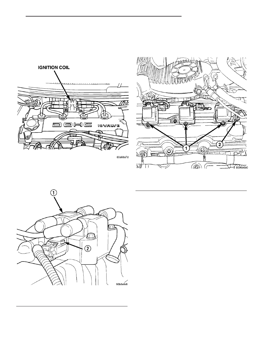
REMOVAL - 4 Cylinder

The electronic ignition coil pack attaches directly

to the valve cover (Fig. 5).

(1) Diconnect the negative battery cable.
(2) Disconnect electrical connector from coil pack

(Fig. 6).

(3) Remove spark plug cables, twist and pull

cables to remove.

(4) Remove coil pack mounting bolts.
(5) Remove coil pack.

REMOVAL - 2.7L

(1) Prior to removing the ignition coils, spray com-

pressed air around the coil area and spark plug (Fig.
7).

(2) Remove electrical connector from ignition coil.
(3) Remove 2 fasteners from ignition coil assembly.
(4) Remove ignition coil assembly (Fig. 8).

INSTALLATION

INSTALLATION - 4 CYLINDER

The electronic ignition coil pack attaches directly

to the valve cover (Fig. 5).

(1) Install coil pack on valve cover.
(2) Install bolts and tighten bolts to N·m 11.8 (105

in. lbs.).

(3) Connect the electrical connector (Fig. 6).
(4) Transfer spark plug cables to new coil pack.

The coil pack towers are numbered with the cylinder
identification. Be sure the ignition cables snap onto
the towers.

INSTALLATION - 2.7L

(1) Install ignition coil assembly for spark plug

(Fig. 8).

(2) Install coil screws and tighten to 6.2 N·m (55

in. lbs.).

Fig. 5 IGNITION COIL 4 CYLINDER

Fig. 6 Ignition Coil Connector

1 - COIL
2 - LOCKING TAB

Fig. 7 IGNITION COILS, COIL CAPACITOR

1 - Ignition Coils
2 - Ignition Capacitor

JR

IGNITION CONTROL

8I - 5

IGNITION COIL (Continued)

(3) Connect the electrical connector.

IGNITION COIL CAPACITOR

DESCRIPTION

There is a coil capacitor added to each bank of cyl-

inders for radio noise suppression.

REMOVAL

(1) Remove the negative battery cable.
(2) Disconnect the electrical connector (Fig. 9).
(3) Remove nut and capacitor.

INSTALLATION

(1) Install capacitor and tighten nut (Fig. 9).
(2) Attach electrical connector to capacitor.
(3) Install the negative battery cable.

KNOCK SENSOR

DESCRIPTION

The knock sensor threads into the cylinder block.

The knock sensor is designed to detect engine vibra-
tion that is caused by detonation.

OPERATION

When the knock sensor detects a knock in one of

the cylinders, it sends an input signal to the PCM. In
response, the PCM retards ignition timing for all cyl-
inders by a scheduled amount.

Knock sensors contain a piezoelectric material

which constantly vibrates and sends an input voltage
(signal) to the PCM while the engine operates. As the
intensity of the crystal’s vibration increases, the
knock sensor output voltage also increases.

The voltage signal produced by the knock sensor

increases with the amplitude of vibration. The PCM
receives as an input the knock sensor voltage signal.
If the signal rises above a predetermined level, the
PCM will store that value in memory and retard
ignition timing to reduce engine knock. If the knock
sensor voltage exceeds a preset value, the PCM
retards ignition timing for all cylinders. It is not a
selective cylinder retard.

The PCM ignores knock sensor input during engine

idle conditions. Once the engine speed exceeds a
specified value, knock retard is allowed.

Knock retard uses its own short term and long

term memory program.

Long term memory stores previous detonation

information in its battery-backed RAM. The maxi-
mum authority that long term memory has over tim-
ing retard can be calibrated.

Short term memory is allowed to retard timing up

to a preset amount under all operating conditions (as
long as rpm is above the minimum rpm) except WOT.
The PCM, using short term memory, can respond
quickly to retard timing when engine knock is
detected. Short term memory is lost any time the
ignition key is turned off.

Fig. 8 IGNITION COIL REMOVAL

Fig. 9 Ignition Coil Capacitor

1 - Ignition Coils
2 - Ignition Capacitor

8I - 6

IGNITION CONTROL

JR

IGNITION COIL (Continued)

NOTE: Over or under tightening affects knock sen-
sor performance, possibly causing improper spark
control.

REMOVAL

REMOVAL - 4 CYLINDER

The knock sensor threads into the side of the cyl-

inder block (Fig. 10).

(1) Disconnect electrical connector from knock sen-

sor.

(2) Use a crow foot socket to remove the knock

sensors.

REMOVAL - 2.7L

The sensors screws into the cylinder block, directly

below the intake manifold.

(1) Remove intake manifold plenum refer to the

Engine section.

(2) Remove the passenger side cylinder head, refer

to the Engine section.

(3) Disconnect electrical connector from knock sen-

sor (Fig. 11).

(4) Use a crows foot socket to remove the knock

sensors.

INSTALLATION

INSTALLATION - 4 CYLINDER

The knock sensor threads into the side of the cyl-

inder block in front of the starter (Fig. 10).

(1) Install knock sensor. Tighten knock sensor to

10 N·m (7 ft. lbs.) torque. Over or under tighten-
ing effects knock sensor performance, possibly
causing improper spark control.

(2) Attach electrical connector to knock sensor.

INSTALLATION - 2.7L

The sensors screws into the cylinder block, directly

below the intake manifold.

(1) Install knock sensor (Fig. 11). Tighten knock

sensor to 10 N·m (7 ft. lbs.) torque. Over or under
tightening effects knock sensor performance
resulting in possible improper spark control.

(2) Install the passenger side cylinder head, refer

to the Engine section.

(3) Attach electrical connector to knock sensor.
(4) Install intake manifold plenum. Refer to the

Engine section.

SPARK PLUG

DESCRIPTION

DESCRIPTION - STANDARD 4 CYLINDER

All engines use resistor spark plugs. They have

resistance values ranging from 6,000 to 20,000 ohms
when checked with at least a 1000 volt spark plug
tester.

Do not use an ohm meter to check the resis-

tance of the spark plugs. This will give an inac-
curate reading.

Refer to the Specifications section for gap and type

of spark plug.

Fig. 10 KNOCK SENSOR - 4 CYLINDER

Fig. 11 KNOCK SENSOR 2.7 L

1 - KNOCK SENSOR

JR

IGNITION CONTROL

8I - 7

KNOCK SENSOR (Continued)

DESCRIPTION - PLATINUM PLUGS

The V6 engines use platinum resistor spark plugs.

They have resistance values of 6,000 to 20,000 ohms
when checked with at least a 1000 volt tester. For
spark plug identification and specifications, Refer to
the Specifications section.

Do not use an ohm meter to check the resis-

tance of the spark plugs. This will give an inac-
curate reading.

When the spark plugs use a single or double plat-

inum tips and they have a recommended service life
of 100,000 miles for normal driving conditions per
schedule A in this manual. The spark plugs have a
recommended service life of 75,000 miles for severe
driving conditions per schedule B in this manual. A
thin platinum pad is welded to both or just the cen-
ter electrode end(s) as shown in (Fig. 12). Extreme
care must be used to prevent spark plug cross
threading, mis-gapping (Fig. 13) and ceramic insula-
tor damage during plug removal and installation.

CAUTION: Cleaning of the platinum plug may dam-
age the platinum tip.

SPARK PLUG CABLE

DESCRIPTION

Spark Plug cables are sometimes referred to as

secondary ignition wires. The wires transfer electri-
cal current from the ignition coil pack to individual
spark plugs at each cylinder. The resistive spark plug
cables are of nonmetallic construction. The cables
provide suppression of radio frequency emissions
from the ignition system.

Check the spark plug cable connections for good

contact at the coil, and spark plugs. Terminals should
be fully seated. The insulators should be in good con-
dition and should fit tightly on the coil, and spark
plugs. Spark plug cables with insulators that are
cracked or torn must be replaced.

Clean Spark Plug cables with a cloth moistened

with a non-flammable solvent. Wipe the cables dry.
Check for brittle or cracked insulation. The spark
plug cables and spark plug boots are made from high
temperature materials.

REMOVAL - 2.0/2.4L

Failure to route the cables properly could cause the

radio to reproduce ignition noise, cross ignition of the
spark plugs or short circuit the cables to ground.

Remove spark plug cable from coil first.
Always remove the spark plug cable by grasping

the top of the spark plug insulator, turning the boot
1/2 turn and pulling straight up in a steady motion.

INSTALLATION - 2.0/2.4L

Failure to route the cables properly could cause the

radio to reproduce ignition noise, cross ignition of the
spark plugs or short circuit the cables to ground.
Install spark plug insulators over spark plugs.
Ensure the top of the spark plug insulator covers the
upper end of the spark plug tube, then connect the
other end to coil pack.

Fig. 12 Platinum Pads

1 - APPLY ANTI-SEIZE COMPOUND HERE ONLY
2 - PLATINUM SPARK SURFACE

Fig. 13 Setting Spark Plug Electrode Gap

1 - TAPER GAUGE

8I - 8

IGNITION CONTROL

JR

SPARK PLUG (Continued)


Content   ..  333  334  335  336   ..