Chrysler Sebring, Stratus sedan, Sebring Convertible. Manual - part 325


  Index      Chrysler     Chrysler Sebring, Stratus sedan, Sebring Convertible - service repair manual 2001-2007 year


Search            


Content   ..  323  324  325  326   ..


Chrysler Sebring, Stratus sedan, Sebring Convertible. Manual - part 325


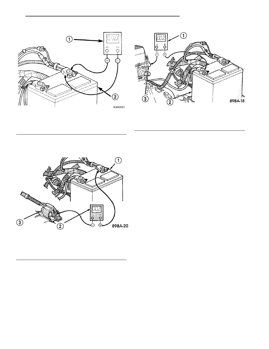
nection at the starter solenoid B(+) terminal stud.
Repeat the test. If the reading is still above 0.2 volt,
replace the faulty battery positive cable.

(4) Connect the voltmeter to measure between the

battery negative cable terminal clamp and a good
clean ground on the engine block (Fig. 11). Rotate
and hold the ignition switch in the Start position.
Observe the voltmeter. If the reading is above 0.2
volt, clean and tighten the battery negative cable
eyelet terminal connection to the engine block.
Repeat the test. If the reading is still above 0.2 volt,
replace the faulty battery negative cable.

REMOVAL

(1) Turn the ignition switch to the Off position. Be

certain that all electrical accessories are turned off.

(2) Disconnect and isolate the remote battery neg-

ative cable terminal.

(3) One at a time, trace and disconnect the battery

cable retaining pushpins, fasteners and routing clips
until the cables are free from the vehicle.

(4) Feed the battery cable assembly out of the

vehicle.

INSTALLATION

(1) Position the battery cable in the vehicle.
(2) One at a time, install the battery cable retain-

ing pushpins, fasteners and routing clips until the
cable is installed exactly in the factory installed loca-
tion in the vehicle. Refer to the Wiring Diagram sec-
tion of the service manual for reference.

(3) Connect the battery negative cable terminal.

BATTERY TRAY

DESCRIPTION

The battery is placed in a steel tray located in the

left front corner of the vehicle (Fig. 12). A hole in the
bottom of the battery tray is fitted with a battery
temperature sensor. Refer to Charging System for
more information on the battery temperature sensor.
Refer to Battery Hold down for more information on
hold down hardware.

OPERATION

The battery tray provides a secure mounting loca-

tion and supports the battery. On some vehicles, the
battery tray also provides the anchor point/s for the
battery holddown hardware. The battery tray and

Fig. 9 Test Battery Positive Connection Resistance -

Typical

1 - VOLTMETER
2 - BATTERY

Fig. 10 Test Battery Positive Cable Resistance -

Typical

1 - BATTERY
2 - VOLTMETER
3 - STARTER MOTOR

Fig. 11 Test Ground Circuit Resistance - Typical

1 - VOLTMETER
2 - BATTERY
3 - ENGINE GROUND

JR

BATTERY SYSTEM

8F - 15

BATTERY CABLES (Continued)

the battery holddown hardware combine to secure
and stabilize the battery in the engine compartment,
which prevents battery movement during vehicle
operation. Unrestrained battery movement during
vehicle operation could result in damage to the vehi-
cle, the battery, or both.

REMOVAL

(1) Disconnect and isolate the remote negative bat-

tery cable.

(2) Remove the battery from the vehicle (Refer to 8

-

ELECTRICAL/BATTERY

SYSTEM/BATTERY

-

REMOVAL).

(3) Remove the left headlamp assembly from the

vehicle (Refer to 8 - ELECTRICAL/LAMPS/LIGHT-
ING - EXTERIOR/HEADLAMP UNIT - REMOVAL).

(4) Remove the battery tray retaining bolts (Fig.

13) and remove the battery tray from the vehicle.

INSTALLATION

(1) Install the battery tray and retaining bolts.

Torque the bolts to 14 N·m (160 in. lbs.).

(2) Install the battery in the vehicle (Refer to 8 -

ELECTRICAL/BATTERY

SYSTEM/BATTERY

-

INSTALLATION).

(3) Install the left headlamp assembly in the vehi-

cle (Refer to 8 - ELECTRICAL/LAMPS/LIGHTING -
EXTERIOR/HEADLAMP UNIT - INSTALLATION).

(4) Connect the remote negative battery cable.

BATTERY HEATER BLANKET

DESCRIPTION

A heater blanket (Fig. 14) is used to improve the

battery cold-start ability. This blanket operates on

Fig. 12 JR Battery Tray and Holddown Hardware

1 - BATTERY HOLDOWN STRAP
2 - BATTERY HOLDOWN STRAP

3 - BATTERY HEATER BLANKET
4 - BATTERY TRAY

Fig. 13 JR Battery Tray

1 - BATTERY TRAY RETAINING FASTENER LOCATIONS

8F - 16

BATTERY SYSTEM

JR

BATTERY TRAY (Continued)

110 volt AC current and is used with Alaska and
Canada cold weather packages.

The heater blanket cannot be adjusted or repaired.

If the blanket is faulty or damaged it must be
replaced.

OPERATION

The temperature of the battery can affect battery

performance. Only DAIMLERCHRYSLER approved
battery blanket/block heater combination should be
used. The battery blanket heater is designed to pro-
vide optimum charging system performance in very
cold ambient temperatures below -17.8°C (0°F).

DIAGNOSIS AND TESTING - BATTERY HEATER
BLANKET

(1) Remove the battery heater blanket from the

battery (Refer to 8 - ELECTRICAL/BATTERY SYS-
TEM/THERMAL GUARD - REMOVAL).

(2) Clean the battery heater blanket with baking

soda solution and wipe dry.

(3) Inspect blanket for cuts, abrasion or other

damage. If heater is damaged replace.

(4) Position the heater flat and re-connect the

blanket heater to the vehicles electrical system.

(5) Connect the 110 volt AC power cord to 110 volt

source for a maximum of 3 minutes.

(6) Disconnect the 110 volt power cord.
(7) Immediately feel the heater blanket on the

inside, it should be warm to the touch. If warm the
heater is OK, if not OK proceed.

(8) Disconnect the heater blanket from the vehicles

electrical system. Using an Ohmmeter, connect the
leads across the two wire terminals coming from the
heater blanket. A resistance value of 220 to 280 ohms
should be present. If not replace the blanket. If OK
proceed.

(9) Ensure that the 110 volt AC power cord is sup-

pling voltage to the heater blanket. If OK replace the
heater blanket. If not verify the 110 volt AC power
from another source. Inspect the power cord for dam-
age and replace if necessary.

REMOVAL

(1) Remove the battery and the battery heater

blanket from the battery tray as a unit (Refer to 8 -
ELECTRICAL/BATTERY

SYSTEM/BATTERY

-

REMOVAL).

(2) Carefully slide the heater blanket straight off

the battery case (Fig. 15).

INSTALLATION

(1) Clean and inspect the battery heater blanket.
(2) Install the battery heater blanket on the bat-

tery case.

(3) Install the battery and the battery heater blan-

ket into the battery tray as a unit (Refer to 8 -
ELECTRICAL/BATTERY

SYSTEM/BATTERY

-

INSTALLATION).

Fig. 14 JR Battery Heater Blanket

1 - BATTERY HEATER BLANKET

Fig. 15 Battery Heater Blanket

1 - BATTERY HEATER BLANKET

JR

BATTERY SYSTEM

8F - 17

BATTERY HEATER BLANKET (Continued)

CHARGING

TABLE OF CONTENTS

page

page

CHARGING

DESCRIPTION - CHARGING SYSTEM

. . . . . . . 18

OPERATION - CHARGING SYSTEM

. . . . . . . . . 18

DIAGNOSIS AND TESTING - ON-BOARD

DIAGNOSTIC SYSTEM

. . . . . . . . . . . . . . . . . 19

SPECIFICATIONS

GENERATOR

. . . . . . . . . . . . . . . . . . . . . . . . 20

TORQUE

. . . . . . . . . . . . . . . . . . . . . . . . . . . . 20

GENERATOR

DESCRIPTION

. . . . . . . . . . . . . . . . . . . . . . . . . 20

OPERATION

. . . . . . . . . . . . . . . . . . . . . . . . . . . 20

REMOVAL

REMOVAL - 4 CYLINDER

. . . . . . . . . . . . . . . 20

REMOVAL - 2.7L

. . . . . . . . . . . . . . . . . . . . . . 22

INSTALLATION

INSTALLATION - 4 CYLINDER

. . . . . . . . . . . . 22

INSTALLATION - 2.7L

. . . . . . . . . . . . . . . . . . 22

VOLTAGE REGULATOR

DESCRIPTION

. . . . . . . . . . . . . . . . . . . . . . . . . 23

OPERATION

. . . . . . . . . . . . . . . . . . . . . . . . . . . 23

CHARGING

DESCRIPTION - CHARGING SYSTEM

The charging system consists of:
• Generator

• Decoupler Pulley (If equipped)

• Electronic Voltage Regulator (EVR) circuitry

within the Powertrain Control Module (PCM)

• Ignition switch (refer to the Ignition System sec-

tion for information)

• Battery (refer to the Battery section for informa-

tion)

• Ambient Air Temperature (If equipped)

• Inlet Air Temperature (calculated battery tem-

perature)(If equipped)

• Voltmeter (refer to the Instrument Cluster sec-

tion for information if equipped)

• Wiring harness and connections (refer to the

Wiring section for information)

• Accessory drive belt (refer to the Cooling section

for more information)

• Battery Temperature sensor (if equipped)

OPERATION - CHARGING SYSTEM

The charging system is turned on and off with the

ignition switch. The system is on when the engine is
running and the ASD relay is energized. The ASD
relay is energized when the PCM grounds the ASD
control circuit. This voltage is connected through the
PCM or IPM (intelligent power module) (if equipped)
and supplied to one of the generator field terminals
(Gen. Source +) at the back of the generator.

The generator is driven by the engine through a

serpentine

belt

and

pulley

or

decoupler

pulley

arrangement.

The amount of DC current produced by the gener-

ator is controlled by the EVR (field control) circuitry

contained within the PCM. This circuitry is con-
nected in series with the second rotor field terminal
and ground.

An Ambient air temperature sensor is used to cal-

culate the temperature near the battery. This tem-
perature data, along with data from monitored line
voltage (battery voltage sense circuit), is used by the
PCM to vary the battery charging rate. This is done
by cycling the ground path to control the strength of
the rotor magnetic field. The PCM then compensates
and regulates generator current output accordingly
to maintain system voltage at the targeted system
voltage based on battery temperature.

All vehicles are equipped with On-Board Diagnos-

tics (OBD). All OBD-sensed systems, including EVR
(field control) circuitry, are monitored by the PCM.
Each monitored circuit is assigned a Diagnostic Trou-
ble Code (DTC). The PCM will store a DTC in elec-
tronic memory for certain failures it detects and
illuminate the (MIL) lamp. Refer to On-Board Diag-
nostics in the Electronic Control Modules(Refer to 8 -
ELECTRICAL/ELECTRONIC

CONTROL

MOD-

ULES/POWERTRAIN

CONTROL

MODULE

-

DESCRIPTION) section for more DTC information.

The Charging system “Battery” light indicates

problems with the charging system (voltage too high/
low, generator failure, etc.). If an extreme condition is
indicated, the lamp will be illuminated. The signal to
activate the lamp is sent via the PCI bus circuits.
The lamp is located on the instrument panel. Refer
to the Instrument Cluster section for additional infor-
mation.

The PCM uses the ambient air temperature sensor

to control the charge system voltage. This tempera-
ture, along with data from monitored line voltage, is
used by the PCM to vary the battery charging rate.
The system voltage is higher at cold temperatures

8F - 18

CHARGING

JR


Content   ..  323  324  325  326   ..