Chrysler Sebring, Stratus sedan, Sebring Convertible. Manual - part 261


  Index      Chrysler     Chrysler Sebring, Stratus sedan, Sebring Convertible - service repair manual 2001-2007 year


Search            


Content   ..  259  260  261  262   ..


Chrysler Sebring, Stratus sedan, Sebring Convertible. Manual - part 261


JUMP STARTING

STANDARD PROCEDURE - JUMP STARTING

WARNING: DO NOT JUMP START A FROZEN BAT-
TERY, PERSONAL INJURY CAN RESULT. DO NOT
JUMP START WHEN MAINTENANCE FREE BAT-
TERY INDICATOR DOT IS YELLOW OR BRIGHT
COLOR. DO NOT JUMP START A VEHICLE WHEN
THE BATTERY FLUID IS BELOW THE TOP OF LEAD
PLATES.

DO

NOT

ALLOW

JUMPER

CABLE

CLAMPS TO TOUCH EACH OTHER WHEN CON-
NECTED TO A BOOSTER SOURCE. DO NOT USE
OPEN FLAME NEAR BATTERY. REMOVE METALLIC
JEWELRY WORN ON HANDS OR WRISTS TO AVOID
INJURY BY ACCIDENTAL ARCING OF BATTERY
CURRENT. WHEN USING A HIGH OUTPUT BOOST-
ING DEVICE, DO NOT ALLOW BATTERY VOLTAGE
TO EXCEED 16 VOLTS. REFER TO INSTRUCTIONS
PROVIDED WITH DEVICE BEING USED.

CAUTION:

When

using

another

vehicle

as

a

booster, do not allow vehicles to touch. Electrical
systems can be damaged on either vehicle.

TO JUMP START A DISABLED VEHICLE:

(1) Raise hood on disabled vehicle and visually

inspect engine compartment for:

• Battery cable clamp condition, clean if necessary.

• Frozen battery.

• Yellow or bright color test indicator, if equipped.

• Low battery fluid level.

• Generator drive belt condition and tension.

• Fuel fumes or leakage, correct if necessary.

CAUTION: If the cause of starting problem on dis-
abled vehicle is severe, damage to booster vehicle
charging system can result.

(2) When using another vehicle as a booster

source, park the booster vehicle within cable reach.
Turn off all accessories, set the parking brake, place
the automatic transmission in PARK or the manual
transmission in NEUTRAL and turn the ignition
OFF.

(3) On disabled vehicle, place gear selector in park

or neutral and set park brake. Turn off all accesso-
ries.

(4) Connect jumper cables to booster battery. RED

clamp to positive terminal (+). BLACK clamp to neg-
ative terminal (-). DO NOT allow clamps at opposite
end of cables to touch, electrical arc will result.
Review all warnings in this procedure.

(5) On disabled vehicle, connect RED jumper cable

clamp to positive (+) terminal. Connect BLACK
jumper cable clamp to engine ground as close to the
ground cable attaching point as possible (Fig. 8).

(6) Start the engine in the vehicle which has the

booster battery, let the engine idle a few minutes,
then start the engine in the vehicle with the dis-
charged battery.

CAUTION: Do not crank starter motor on disabled
vehicle for more than 15 seconds, starter will over-
heat and could fail.

(7) Allow battery in disabled vehicle to charge to

at least 12.4 volts (75% charge) before attempting to
start engine. If engine does not start within 15 sec-
onds, stop cranking engine and allow starter to cool
(15 minutes), before cranking again.

DISCONNECT CABLE CLAMPS AS FOLLOWS:

• Disconnect BLACK cable clamp from engine

ground on disabled vehicle.

• When using a Booster vehicle, disconnect

BLACK cable clamp from battery negative terminal.

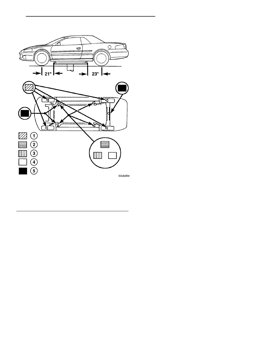
Fig. 7 HOISTING AND JACKING POINTS - JR-27

1 - DRIVE ON LIFT
2 - FRAME CONTACT LIFT (SINGLE POST)
3 - CHASSIS LIFT (DUAL POST)
4 - OUTBOARD LIFT (DUAL LIFT)
5 - FLOOR JACK

JR

LUBRICATION & MAINTENANCE

0 - 21

HOISTING (Continued)

Disconnect RED cable clamp from battery positive
terminal.

• Disconnect RED cable clamp from battery posi-

tive terminal on disabled vehicle.

TOWING

STANDARD PROCEDURE - TOWING

WARNINGS AND PRECAUTIONS

WARNING: DO NOT ALLOW TOWING ATTACHMENT
DEVICES TO CONTACT THE FUEL TANK OR LINES,
FUEL LEAK CAN RESULT. DO NOT LIFT OR TOW
VEHICLE

BY FRONT

OR

REAR

BUMPER,

OR

BUMPER ENERGY ABSORBER UNITS. DO NOT
VENTURE UNDER A LIFTED VEHICLE IF NOT SUP-
PORTED PROPERLY ON SAFETY STANDS. DO NOT
ALLOW PASSENGERS TO RIDE IN A TOWED VEHI-
CLE. USE A SAFETY CHAIN THAT IS INDEPENDENT
FROM THE TOWING ATTACHMENT DEVICE.

CAUTION: Do not damage brake lines, exhaust sys-
tem, shock absorbers, sway bars, or any other
under vehicle components when attaching towing
device to vehicle. Do not attach towing device to
front or rear suspension components. Do not
secure vehicle to towing device by the use of front
or

rear

suspension

or

steering

components.

Remove or secure loose or protruding objects from
a damaged vehicle before towing. Refer to state and
local rules and regulations before towing a vehicle.

Do not allow weight of towed vehicle to bear on
lower fascia, air dams, or spoilers.

RECOMMENDED TOWING EQUIPMENT

To avoid damage to bumper fascia and air dams

use of a flat bed towing device or wheel lift (Fig. 9) is
recommended. When using a wheel lift towing device,
be sure the unlifted end of disabled vehicle has at
least 100 mm (4 in.) ground clearance. If minimum
ground clearance cannot be reached, use a towing
dolly. If a flat bed device is used, the approach angle
should not exceed 15 degrees.

GROUND CLEARANCE

CAUTION: If vehicle is towed with wheels removed,
install lug nuts to retain brake drums or rotors.

A towed vehicle should be raised until the lifted

wheels are a minimum 100 mm (4 in.) from the
ground. Be sure there is at least 100 mm (4 in.)
clearance between the tail pipe and the ground. If
necessary, remove the wheels from the lifted end of
the vehicle and lower the vehicle closer to the
ground, to increase the ground clearance at the rear
of the vehicle. Install lug nuts on wheel attaching
studs to retain brake drums or rotors.

LOCKED VEHICLE TOWING

When a locked vehicle must be towed with the

front wheels on the ground, use a towing dolly or flat
bed hauler.

FLAT TOWING WITH TOW BAR

• Three speed automatic transaxle vehicles can be

flat towed at speeds not to exceed 40 km/h (25 mph)
for not more than 25 km (15 miles). The steering col-
umn must be unlocked and gear selector in neutral.

• Five speed manual transaxle vehicles can be flat

towed at any legal highway speed for extended dis-
tances. The gear selector must be in the neutral posi-
tion.

Fig. 8 Jumper Cable Clamp Connections

1 - BATTERY POSITIVE CABLE
2 - POSITIVE JUMPER CABLE
3 - TEST INDICATOR
4 - BATTERY NEGATIVE CABLE
5 - BATTERY
6 - NEGATIVE JUMPER CABLE
7 - ENGINE GROUND

Fig. 9 Recommended Towing Equipment

1 - WHEEL LIFT
2 - FLAT BED

0 - 22

LUBRICATION & MAINTENANCE

JR

JUMP STARTING (Continued)

FLAT BED TOWING TIE DOWNS

CAUTION: Do not tie vehicle down by attaching
chains or cables to suspension components or
engine mounts, damage to vehicle can result.

JR vehicles can be tied to a flat bed device using

the reinforced loops located under the front and rear
bumpers on the drivers side of the vehicle. There are
also four reinforced elongated holes for T or R hooks
located on the bottom of the front frame rail torque
boxes behind the front wheels and forward of the
rear wheels inboard of the rocker panel weld seam.

TOWING – FRONT WHEEL LIFT

DaimlerChrysler Corporation recommends that a

vehicle be towed with the front end lifted, whenever
possible. A 90 cm (36 in.) length of 4x4 wood beam

can be placed between the wheel lift device and the
bottom of the fascia to prevent damage to vehicle
during the lifting operation. The beam can removed
after lifting the front of the vehicle.

TOWING – REAR WHEEL LIFT

If a vehicle cannot be towed with the front wheels

lifted, the rear wheels can be lifted provided the fol-
lowing guide lines are observed.

CAUTION: Do not use steering column lock to
secure steering wheel during towing operation.

• Unlock steering column and secure steering

wheel in straight ahead position with a clamp device
designed for towing.

• Place front wheels on a towing dolly.

JR

LUBRICATION & MAINTENANCE

0 - 23

TOWING (Continued)


Content   ..  259  260  261  262   ..