Chrysler Sebring, Stratus sedan, Sebring Convertible. Manual - part 157
the monitor run conditions, select the EGR PRE-
TEST in the DRB III
t, OBD II Monitors Menu.
D. 02 SENSOR HEATER MONITOR
This monitor is now continuously running once
the heaters are energized. Pass information will be
processed at power down. For the monitor run
conditions, select the O2S HEATER MON PRE-
TEST in the DRB III
t, OBD II Monitors Menu.
3.2.3
OTHER CONTROLS
AIR INJECTION SYSTEM
During vehicle cold start, the Air Injection Sys-
tem (AIS) delivers a controlled amount of outside
air into the exhaust system, upstream of the cata-
lytic converters, in order to help reduce hydrocar-
bon and carbon monoxide gas emissions.
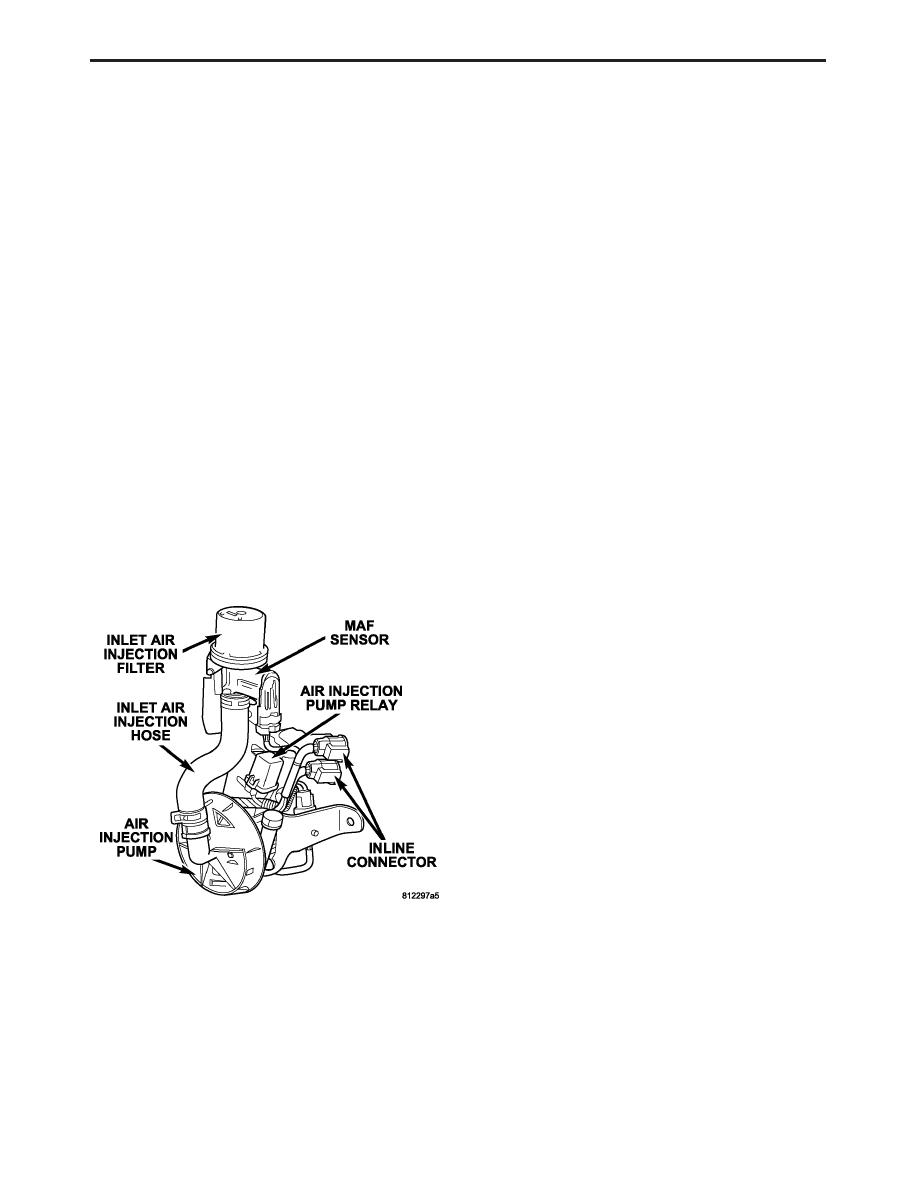
The Air Injection System consists of the following
components:
•
Air Injection Pump
•
Air Injection Pump Relay
•
Air Injection (Nylon) Tube
•
Exhause one-way check valve
•
Inlet Air Injection Filter
•
Inlet Air Injection Hose
•
MAF Sensor
When the Air Injection Pump is activated, air is
drawn into the Air Injection System through the
Inlet Air Injection Filter. The air is then passed
through the MAF Sensor, which monitors the
amount of air that enters the Air Injection System.
The PCM uses the MAF Sensor information to
control Air Pump operation based on feedback from
the front 02 sensor. After passing through the MAF
Sensor, air travels through the Inlet Air Injection
hose, into the Air Pump (where it is compressed),
through the Air Injection (Nylon) Tube, past the
Exhaust one-way check valve, and into the exhaust
system.
CHARGING SYSTEM
The charging system is turned on when the
engine is started. The Generator field is control by
the PCM using a 12-volt high-side driver and a body
ground circuit. The Generator output voltage is
determined by the PCM. When more system voltage
is needed, the PCM will applies a longer duty cycle
using the 12-volt high-side drive and shortens duty
cycle or none at all when less voltage is needed.
O2 SENSOR
The O2 system with ignition on and engine off
has a normalized O2 voltage of around 5 volts as
displayed on the DRBIII or measured with a high
impedance voltmeter. As the O2 sensor starts gen-
erating a signal the voltage will move towards 2.5
volts. The voltage will typically vary between 2.5
volts and 3.5 volts on a normal running engine. The
goal voltage is also typically between 2.5 and 3.5
volts. This implies that the 0-volt through 1-volt
range that you are used to is still valid, only it is
shifted up by a 2.5 volt offset. This 2.5 volt supply is
being delivered through the sensor return line.
SPEED CONTROL SYSTEM
The PCM controls vehicle speed by operation of
the speed control servo vacuum and vent solenoids.
Energizing the vacuum solenoid applies vacuum to
the servo to increase throttle position. Operation of
the vent solenoid slowly releases the vacuum allow-
ing throttle position to decrease. A special vacuum
dump solenoid allows immediate release of the
throttle during speed control operation.
Speed control may be cancelled by braking, driver
input using the speed control switches, shifting into
neutral, excessive engine speed (wheels spinning),
or turning the ignition off.
NOTE: If two speed control switches are
selected simultaneously, the PCM will detect
an illegal switch operation and turn the speed
control off.
NATURAL VACUUM LEAK DETECTION (NVLD) –
IF EQUIPPED
The Natural Vacuum Leak Detection (NVLD)
system is the next generation evaporative leak
detection system that will first be used on vehicles
equipped with the Powertrain Control Module
(PCM) or Next Generation Controller (NGC) start-
ing in 2002 M.Y. This new system replaces the leak
detection pump as the method of evaporative sys-
tem leak detection. The current CARB requirement
is to detect a leak equivalent to a 0.020
9 (0.5 mm)
5
GENERAL INFORMATION