Chrysler RG Voyager. Manual - part 657
(22) Remove two nuts securing brake lamp switch
bracket to pedal assembly. Remove bracket.
(23) Disconnect wiring connector connecting vehi-
cle wiring harness connector to pedal wiring harness
(Fig. 58).
(24) Unfasten routing clips retaining vehicle wir-
ing harness to pedal wiring harness (Fig. 58).
(25) Remove power brake booster input rod from
brake pedal pin by performing following:
(a) Position small screwdriver between center
tang on retaining clip and brake pedal pin (Fig.
59).
(b) Rotate screwdriver, moving retaining clip
center tang enough to allow it to pass over end of
brake pedal pin, then slide retaining clip off brake
pedal pin.
(c) Discard retaining clip. Retaining clip must
not be reused. Install NEW retaining clip
when assembling.
(d) Slide booster input rod off pedal pin.
(26) Disconnect pedal adjuster cable at brake
pedal adjustment gear box (Fig. 60).
(27) Remove pedal adjuster cable from routing loop
on steering column bracket (Fig. 60), then pull gear
box end of cable upward, out of steering column
bracket, and down right side of pedals assembly.
(28) Remove four nuts attaching power brake
booster and pedals assembly to dash panel (Fig. 61).
(29) Remove two upper mounting bolts attaching
pedals assembly to steering column support bracket
on dash.
(30) Disconnect throttle cable retainer at accelera-
tor pedal, then remove cable from pedal.
(31) Remove adjustable pedals assembly.
INSTALLATION
(1) Install
adjustable
pedals
assembly
under
instrument panel.
(2) Attach throttle cable to accelerator pedal using
cable retainer.
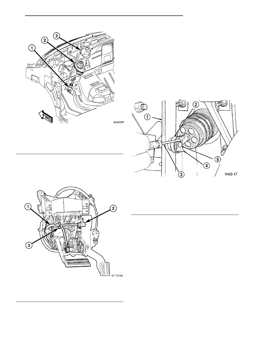
Fig. 57 Intermediate Shaft Dash Seal And Silencer
Shell
1 - INTERMEDIATE SHAFT
2 - DASH SEAL
3 - SILENCER SHELL
Fig. 58 Wiring Harness Connection
1 - VEHICLE WIRING HARNESS
2 - WIRING CONNECTOR
3 - ROUTING LOOP
Fig. 59 Input Rod Brake Pedal Retaining Clip
Removal
1 - BRAKE PEDAL
2 - INPUT ROD
3 - SCREWDRIVER
4 - RETAINING CLIP
5 - BRAKE PEDAL PIN
RS
BRAKES - BASE
5 - 41
PEDALS - ADJUSTABLE (Continued)