Chrysler RG Voyager. Manual - part 493


  Index      Chrysler     Chrysler RG Voyager - service repair manual 2005 year


Search            


Content   ..  491  492  493  494   ..


Chrysler RG Voyager. Manual - part 493


Injector opens (start of injection)

The solenoid valve is energized with the pickup

current which serves to ensure that it open quickly.
The force exerted by the triggered solenoid now
exceeds that of the valve spring and the armature
opens the bleed orifice. Almost immediately, the high-
level pick-up current is reduced to the lower holding
current required for the electromagnet. This is possi-
ble due to the magnetic circuit’s air gap now being
smaller. When the bleed orifice opens, fuel can flow
from the valve control chamber into the cavity situ-
ated above it, and from there via the fuel return to
the tank. The bleed orifice prevents complete pres-
sure balance, and the pressure in the valve control
chamber sinks as a result. This leads to the pressure
in the valve-control chamber being lower than that in
the nozzle’s chamber volume which is still at the
same pressure level as the rail. The reduced pressure
in the valve-control chamber causes a reduction in
the force exerted on the control plunger, the nozzle
needle opens as a result, and injection starts (Fig. 4).

Injector opens fully

The control plunger reaches its upper stop where it

remains supported by a cushion of fuel which is gen-
erated by the flow of fuel between the bleed and feed
orifices. The injector nozzle has now opened fully,
and the fuel is injected into the combustion chamber
at a pressure almost equal to that in the fuel rail
(Fig. 4).

Injector closes (end of injection)

As soon as the solenoid valve is no longer trig-

gered, the valve spring forces the armature down-
wards and the ball closes the bleed orifice. The
armature is a 2–piece design. Here, although the
armature plate is guided by a driver shoulder in its
downward movement, it can “overspring” with the
return spring so that it exerts no downwards-acting
forces on the armature and the ball. The closing of
the bleed orifice lead to pressure build up in the con-
trol chamber via the input from the feed orifice. This
pressure is the same as that in the rail and exerts an
increased force on the control plunger through its
end face. This force, together with that of the spring,
now exceeds the force exerted by the chamber volume
and the nozzle needle closes. Injection ceases as soon
as the nozzle needle comes up against its bottom stop
again (Fig. 4).

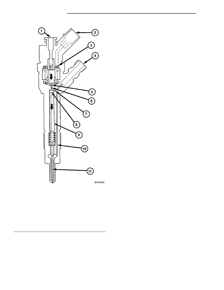
Fig. 4 INJECTOR COMPONENTS

1 - INJECTOR CLOSED (AT-REST STATUS)
2 - ELECTRICAL CONNECTION
3 - TRIGGERING ELEMENT (SOLENOID VALVE)
4 - FUEL INLET (HIGH PRESSURE) FROM THE RAIL
5 - VALVE BALL
6 - BLEED ORIFICE
7 - FEED ORIFICE
8 - VALVE CONTROL CHAMBER
9 - VALVE CONTROL PLUNGER
10 - FEED PASSAGE TO THE NOZZLE
11 - NOZZLE NEEDLE

14a - 20

FUEL INJECTION

RG

FUEL INJECTOR (Continued)

STANDARD PROCEDURE - INJECTOR BORE
CLEANING

(1) Screw the injector nozzle bore plug onto the

threaded extention.

(2) Seat the plug into the injector nozzle bore and

remove threaded extention (Fig. 5).

(3) Using the abrasive blade roller, clean the injec-

tor bore (Fig. 6).

NOTE: Before blowing the debris out of the bore,
insert the threaded extention onto the the plug and
press down to prevent debris from entering the
combustion chamber.

(4) Install the threaded extention onto the bore

plug and press down while blowing the material
away from the injector seat (Fig. 5).

NOTE: Do Not apply antiseize compound near the
fuel injector nozzle.

NOTE: Repeated mounting of the return fuel hose
retaining ring is not permitted

(5) Carefully clean and lubracate the injector body

with antiseize compound before installation (Fig. 7).

Fig. 5 FUEL INJECTOR PLUG AND EXTENTION

1 - HANDLE
2 - THREADED EXTENTION
3 - PLUG
4 - O-RING
5 - CYLINDER HEAD

Fig. 6 CYLINDER HEAD INJECTOR BORE

CLEANING

1 - EXTENTION
2 - DOWEL
3 - ABRASIVE BLADE ROLLER
4 - PLUG
5 - O-RING
6 - CYLINDER HEAD

Fig. 7 FUEL INJECTOR

1 - LUBRACATION POINTS
2 - WASHER
3 - SEAL

RG

FUEL INJECTION

14a - 21

FUEL INJECTOR (Continued)

REMOVAL

NOTE: Repeated mounting of the fuel return line
and retaining clip is not permitted.

(1) Disconnect negative battery cable (Refer to 14 -

FUEL SYSTEM - WARNING).

(2) Remove engine cover (Refer to 9 - ENGINE -

REMOVAL)

(Refer

to

9

-

ENGINE

COVER

-

REMOVAL).

(3) Disconnect injector electrical connector.

NOTE: DO NOT use a brush to clean around injec-
tor nozzle. The Injector may become restricted with
debris.

(4) Remove fuel return line from injector (Fig. 8).
(5) Counterhold and remove fuel injector high

pressure line from the injector.

(6) Remove

fuel

injector

retaining

bolt

and

retainer (Fig. 8).

(7) Remove fuel injector from cylinder head (Fig.

8).

CAUTION: If the fuel injectors will not come out of
the cylinder head perform the following steps to
prevent damaging other components.

(8) Assemble and install Injector extractor special

tool VM9075 on to injector and cylinder head (Fig. 9).

(9) Tighten injector extractor center nut until fuel

injector is extracted (Fig. 10).

NOTE: If the injector is still hard to remove, leave
the tool in place with tension on the injector and
liberally spray the injector seat with antiseize lubri-
cant.

(10) Thoroughly clean cylinder head fuel injector

bore (Refer to 14 - FUEL SYSTEM/FUEL INJEC-
TION/FUEL

INJECTOR

-

STANDARD

PROCE-

DURE).

INSTALLATION

WARNING: (Refer to 14 - FUEL SYSTEM - WARN-
ING).

NOTE: Lightly lubricate injector body with antiseize
compound and install fuel injector in cylinder head.
Be sure the copper washer is installed on end of
injector before installing in cylinder head.

NOTE: DO NOT use a brush to clean around injec-
tor nozzle. DO NOT lubricate area around injector
nozzle. The Injector may become restricted with
debris.

Fig. 8 FUEL INJECTOR AND COMPONENTS

1 - FUEL RETURN LINE
2 - ONE WAY VALVE
3 - RETAINING RING
4 - WASHER
5 - O-RING

Fig. 9 FUEL INJECTOR EXTRACTOR

1 - VM9075
2 - FUEL INJECTOR

14a - 22

FUEL INJECTION

RG

FUEL INJECTOR (Continued)

(1) Install fuel injector with new seals.
(2) Install fuel injector retainer and bolt (Fig. 8).

Torque bolt to 32.4 N·m.

(3) Install fuel injector high pressure line, counter-

hold and tighten to 20 N·m (177 lbs. in.)..

NOTE: Repeated mounting of the return line and
clip is not permitted.

(4) Install fuel return line to injector (Fig. 8).
(5) Connect fuel injector electrical connector.
(6) Install engine cover (Refer to 9 - ENGINE -

INSTALLATION).

(7) Connect negative battery cable (Refer to 14 -

FUEL SYSTEM - WARNING).

ACCELERATOR PEDAL
POSITION SENSOR

DESCRIPTION

The accelerator pedal position sensor mounts to

the accelerator pedal bracket (Fig. 11).

OPERATION

The accelerator pedal position sensor contains a

low idle switch and a potentiometer that are oper-
ated by the accelerator pedal. As the accelerator
pedal is depressed, the low idle switch opens and the
potentiometer provides a variable voltage signal to
the engine control module directly proportional to
accelerator pedal position. When the pedal is fully
depressed, the voltage signal is high.

REMOVAL - PEDAL POSITION SENSOR (LHD)

(1) Disconnect negative battery cable.
(2) Disconnect pedal position sensor electrical con-

nector (Fig. 11).

(3) Remove 2 pedal position sensor retaining nuts

(Fig. 11).

(4) Remove pedal position sensor from vehicle.

INSTALLATION - PEDAL POSITION SENSOR
(LHD)

(1) Position pedal position sensor in vehicle.
(2) Install pedal position sensor retaining nuts

(Fig. 11).

(3) Connect pedal position sensor electrical connec-

tor (Fig. 11).

(4) Connect negative battery cable.

Fig. 10 SPECIAL TOOL VM9075

1 - VM9075
2 - FUEL INJECTOR

Fig. 11 ACCELERATOR PEDAL POSITION SENSOR

LOCATION (TYPICAL)

1 - ACCELERATOR PEDAL POSITION SENSOR ELECTRICAL
CONNECTOR
2 - ACCELERATOR PEDAL POSITION SENSOR
3 - ACCELERATOR PEDAL
4 - ACCELERATOR PEDAL MOUNTING BRACKET

RG

FUEL INJECTION

14a - 23

FUEL INJECTOR (Continued)


Content   ..  491  492  493  494   ..