Chrysler RG Voyager. Manual - part 464


  Index      Chrysler     Chrysler RG Voyager - service repair manual 2005 year


Search            


Content   ..  462  463  464  465   ..


Chrysler RG Voyager. Manual - part 464


DIAGNOSIS AND TESTING

DIAGNOSIS AND TESTING - COOLING SYSTEM
PRESSURE CAP

Dip the pressure cap in water. Clean any deposits

off the vent valve or its seat and apply cap to end of
the Pressure Cap Test Adaptor that is included with
the

Cooling

System

Tester

7700.

Working

the

plunger, bring the pressure to 104 kPa (15 psi) on the
gauge. If the pressure cap fails to hold pressure of at
least 97 kPa (14 psi), replace the pressure cap.

CAUTION: The Cooling System Tester Tool is very
sensitive to small air leaks that will not cause cool-
ing system problems. A pressure cap that does not
have a history of coolant loss should not be
replaced just because it leaks slowly when tested
with this tool. Add water to the tool. Turn tool
upside down and recheck pressure cap to confirm
that cap is bad.

If the pressure cap tests properly while positioned

on Cooling System Tester (Fig. 20), but will not hold
pressure or vacuum when positioned on the filler
neck. Inspect the filler neck and cap top gasket for
irregularities that may prevent the cap from sealing
properly.

DIAGNOSIS AND TESTING - PRESSURE
RELIEF TEST

The pressure cap upper gasket (seal) pressure

relief can be checked by removing the overflow hose
at the radiator filler neck nipple (Fig. 21). Attach the
Radiator Pressure Tool to the filler neck nipple and
pump air into the radiator. Pressure cap upper gas-
ket should relieve at 69-124 kPa (10-18 psi) and hold
pressure at 55 kPa (8 psi) minimum.

WARNING: THE WARNING WORDS “DO NOT OPEN
HOT” ON THE RADIATOR PRESSURE CAP IS A
SAFETY PRECAUTION. WHEN HOT, PRESSURE
BUILDS UP IN COOLING SYSTEM. TO PREVENT
SCALDING

OR

INJURY,

THE

RADIATOR

CAP

SHOULD NOT BE REMOVED WHILE THE SYSTEM
IS HOT OR UNDER PRESSURE.

There is no need to remove the radiator cap at any

time except for the following purposes:

(1) Check and adjust coolant freeze point.
(2) Refill system with new coolant.
(3) Conducting service procedures.
(4) Checking for vacuum leaks.

WARNING: IF VEHICLE HAS BEEN RUN RECENTLY,
WAIT 15 MINUTES BEFORE REMOVING CAP. THEN
PLACE A SHOP TOWEL OVER THE CAP AND WITH-
OUT PUSHING DOWN ROTATE COUNTERCLOCK-
WISE TO THE FIRST STOP. ALLOW FLUIDS TO
ESCAPE THROUGH THE OVERFLOW TUBE AND
WHEN THE SYSTEM STOPS PUSHING COOLANT
AND STEAM INTO THE CRS TANK AND PRESSURE
DROPS PUSH DOWN AND REMOVE THE CAP COM-
PLETELY. SQUEEZING THE RADIATOR INLET HOSE
WITH A SHOP TOWEL (TO CHECK PRESSURE)
BEFORE AND AFTER TURNING TO THE FIRST
STOP IS RECOMMENDED.

CLEANING

Use only a mild soap to clean the pressure cap.

Fig. 20 Testing Cooling System Pressure Cap

1 - PRESSURE CAP
2 - PRESSURE TESTER

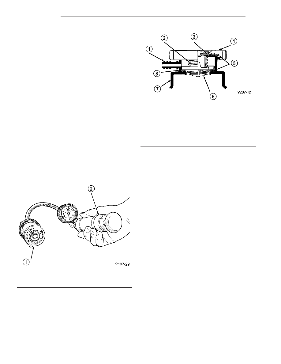
Fig. 21 Radiator Pressure Cap Filler Neck

1 - OVERFLOW NIPPLE
2 - MAIN SPRING
3 - GASKET RETAINER
4 - STAINLESS-STEEL SWIVEL TOP
5 - RUBBER SEALS
6 - VENT VALVE
7 - PRESSURE BOTTLE
8 - FILLER NECK

7a - 24

ENGINE

RG

RADIATOR PRESSURE CAP (Continued)

INSPECTION

Hold the cap in your hand, top side up (Fig. 21).

The vent valve at the bottom of the cap should open.
If the rubber gasket has swollen, preventing the
valve from opening, replace the cap.

Hold the cleaned cap in your hand, upside down.

If any light can be seen between vent valve and the
rubber gasket, replace the cap. Do not use a
replacement cap that has a spring to hold the
vent shut.

A replacement cap must be of the type designed for

coolant reserve systems. This design ensures coolant
return to the radiator.

RADIATOR FAN

DESCRIPTION

The dual radiator fans are mounted to the back

side of the radiator (Fig. 22). The radiator fan consist
of the fan blade, electric motor and a support shroud
which are all serviced as an assembly.

OPERATION

RADIATOR FAN OPERATION CHART

FAN OPERATION AS A FUNCTION OF COOLANT TEMPERATURE

Fan Status

A/C On, High Ambient

A/C ON, Norm Ambient

A/C Off, Norm Ambient

OFF

93°C (200°F)

96°C (205°F)

98°C (208°F)

LOW TO OFF

93°C (200°F)

96°C (205°F)

98°C (208°F)

OFF TO LOW

96°C (205°F)

98°C (208°F)

100°C (212°F)

HI TO LOW

96°C (205°F)

100°C (212°F)

102°C (216°F)

LO TO HIGH

98°C (208°F)

102°C (216°F)

104°C (220°F)

DIAGNOSIS AND TESTING - RADIATOR FAN MOTOR

RADIATOR FAN DIAGNOSIS CHART

CONDITION

POSSIBLE CAUSES

CORRECTION

NOISY RADIATOR
FAN

1. Fan blade loose.

1. Replace fan assembly. (Refer to 7 - COOLING/
ENGINE/RADIATOR FAN - REMOVAL)

2. Fan blade striking a surrounding
object.

2. Locate point of fan blade contact and repair as
necessary.

3. Air obstructions at radiator or A/C
condenser.

3. Remove obstructions and/or clean debris.

4. Electric fan motor defective.

4. Replace fan assembly. (Refer to 7 - COOLING/
ENGINE/RADIATOR FAN - REMOVAL)

ELECTRIC FAN
MOTOR DOES NOT
OPERATE

1. Fan relay, powertrain control
module (PCM), coolant temperature
sensor, or wiring defective.

1. (Refer to Appropriate Diagnostic Information)
Repair as necessary.

2. Defective A/C pressure
transducer.

2. (Refer to Appropriate Diagnostic Information)
Repair as necessary.

ELECTRIC
RADIATOR FAN
OPERATES ALL THE
TIME

1. Fan relay, powertrain control
module (PCM), coolant temperature
sensor or wiring defective.

1. (Refer to Appropriate Diagnostic Information)
Repair as necessary.

2. Check for low coolant level.

2. Add coolant as necessary.

3. Defective A/C pressure
transducer.

3. (Refer to Appropriate Diagnostic Information)
Repair as necessary.

RG

ENGINE

7a - 25

RADIATOR PRESSURE CAP (Continued)

REMOVAL

There are no repairs to be made to the fan or

shroud assembly. If the fan is warped, cracked, or
otherwise damaged, it must be replaced as an assem-
bly (Fig. 22).

(1) Remove the radiator upper crossmember. (Refer

to 23 - BODY/EXTERIOR/GRILLE OPENING REIN-
FORCEMENT - REMOVAL)

(2) Disconnect the radiator fan electrical connec-

tors.

(3) Remove radiator fan(s) retaining screw (Fig.

22).

(4) Remove the radiator fan(s) by lifting upward to

release from mounts.

INSTALLATION

(1) Install the radiator fan(s) into mounts and

attaching clips on the radiator.

(2) Install radiator fan(s) attaching screws (Fig.

22). Tighten to 5 N·m (45 in. lbs.).

(3) Connect the radiator fan(s) electrical connec-

tors.

(4) Install the radiator upper support crossmem-

ber. (Refer to 23 - BODY/EXTERIOR/GRILLE OPEN-
ING REINFORCEMENT - INSTALLATION)

(5) Install the upper radiator mounts to the cross-

member bolts, if removed. Tighten to 8 N·m (70 in.
lbs.).

(6) Install the radiator upper hose to the support

clip (2.4L engine).

HOSE CLAMPS

DESCRIPTION - HOSE CLAMPS

The cooling system uses spring type hose clamps.

If a spring type clamp replacement is necessary,
replace with the original Mopar

t equipment spring

type clamp.

CAUTION: A number or letter is stamped into the
tongue of constant tension clamps. If replacement
is necessary, use only a original equipment clamp
with matching number or letter (Fig. 23).

OPERATION - HOSE CLAMPS

The spring type hose clamp applies constant ten-

sion on a hose connection. To remove a spring type
hose clamp, use Special Tool 6094 or equivalent, con-
stant tension clamp pliers (Fig. 24) to compress the
hose clamp.

Fig. 22 Radiator Fans

1 - SCREWS - RADIATOR FAN ATTACHING
2 - RADIATOR FAN - RIGHT
3 - MOUNT - RIGHT RADIATOR FAN
4 - CLIPS - RADIATOR FAN LOWER
5 - MOUNT - LEFT RADIATOR FAN
6 - RADIATOR FAN - LEFT

Fig. 23 Spring Clamp Size Location

1 - SPRING CLAMP SIZE LOCATION

7a - 26

ENGINE

RG

RADIATOR FAN (Continued)

RADIATOR FAN RELAY

DESCRIPTION

The low and high speed fan relays are mounted to

the upper radiator support above the charge air
cooler (Fig. 25).

OPERATION

The cooling system uses two fans. Both fans oper-

ate at two different speeds, low and high. Depending
on engine coolant temperature and A/C system high
side pressure, the fans operate at either low or high.
The ignition switch supplies voltage to the coil side of
the relay. When the ECM grounds the coil side of the
relay, the contacts close and the battery supplies
power to the fans.

COOLANT SYSTEM HOSES

REMOVAL

REMOVAL - UPPER RADIATOR HOSE

WARNING: THE WARNING WORDS “DO NOT OPEN
HOT” ON THE RADIATOR PRESSURE CAP IS A
SAFETY PRECAUTION. WHEN HOT, PRESSURE
BUILDS UP IN COOLING SYSTEM. TO PREVENT
SCALDING

OR

INJURY,

THE

RADIATOR

CAP

SHOULD NOT BE REMOVED WHILE THE SYSTEM
IS HOT OR UNDER PRESSURE.

(1) Remove engine cover (Refer to 9 - ENGINE -

REMOVAL).

(2) Drain cooling system (Refer to 7 - COOLING/

ENGINE/COOLANT - STANDARD PROCEDURE).

(3) Remove upper radiator hose (Fig. 26).

REMOVAL - LOWER RADIATOR HOSE

WARNING: THE WARNING WORDS “DO NOT OPEN
HOT” ON THE RADIATOR PRESSURE CAP IS A
SAFETY PRECAUTION. WHEN HOT, PRESSURE
BUILDS UP IN COOLING SYSTEM. TO PREVENT
SCALDING

OR

INJURY,

THE

RADIATOR

CAP

SHOULD NOT BE REMOVED WHILE THE SYSTEM
IS HOT OR UNDER PRESSURE.

(1) Drain cooling system (Refer to 7 - COOLING/

ENGINE/COOLANT - STANDARD PROCEDURE).

(2) Remove lower radiator hose (Fig. 26).

REMOVAL - COOLANT BYPASS HOSE

WARNING: THE WARNING WORDS “DO NOT OPEN
HOT” ON THE RADIATOR PRESSURE CAP IS A
SAFETY PRECAUTION. WHEN HOT, PRESSURE
BUILDS UP IN COOLING SYSTEM. TO PREVENT
SCALDING

OR

INJURY,

THE

RADIATOR

CAP

SHOULD NOT BE REMOVED WHILE THE SYSTEM
IS HOT OR UNDER PRESSURE.

(1) Drain cooling system (Refer to 7 - COOLING/

ENGINE/COOLANT - STANDARD PROCEDURE).

(2) Remove the coolant bypass hose (Fig. 26).

Fig. 24 Hose Clamp Tool

1 - HOSE CLAMP TOOL 6094
2 - HOSE CLAMP

Fig. 25 RELAY LOCATIONS

1 - GLOW PLUG RELAY
2 - UPPER RADIATOR SUPPORT
3 - CHARGE AIR COOLER OUTLET HOSE
4 - RADIATOR FAN RELAYS
5 - UPPER RADIATOR HOSE
6 - EGR SOLENOID

RG

ENGINE

7a - 27

HOSE CLAMPS (Continued)


Content   ..  462  463  464  465   ..