Chrysler RG Voyager. Manual - part 448


  Index      Chrysler     Chrysler RG Voyager - service repair manual 2005 year


Search            


Content   ..  446  447  448  449   ..


Chrysler RG Voyager. Manual - part 448


front and rear drive units. The unit is totally sealed
and partially filled with silicone fluid. There is no
adjustment, maintenance or fluid checks required
during the life of the unit.

The overrunning clutch allows the rear wheels to

overrun the front wheels during a rapid front wheel
lock braking maneuver. The overrunning action pre-
vents any feed-back of front wheel braking torque to
the rear wheels. It also allows the braking system to
control the braking behavior as a two wheel drive
(2WD) vehicle.

The overrunning clutch housing has a separate oil

sump and is filled independently from the differen-
tial. The fill plug is located on the side of the over-
running clutch case. When filling the overrunning
clutch with lubricant use Mopar

t ATF+4 (Automatic

Transmission Fluid—Type 9602) or equivalent.

The differential assembly contains a conventional

open differential with hypoid ring gear and pinion
gear set. The hypoid gears are lubricated by SAE
80W-90 gear lubricant.

DIAGNOSIS AND TESTING

DIAGNOSIS AND TESTING - REAR DRIVELINE
MODULE NOISE

Different sources can be the cause of noise that the

rear driveline module assembly is suspected of mak-
ing. Refer to the following causes for noise diagnosis.

DRIVELINE MODULE ASSEMBLY NOISE

The most important part of driveline module ser-

vice is properly identifying the cause of failures and
noise complaints. The cause of most driveline module
failures is relatively easy to identify. The cause of
driveline module noise is more difficult to identify.

If vehicle noise becomes intolerable, an effort

should be made to isolate the noise. Many noises that
are reported as coming from the driveline module
may actually originate at other sources. For example:

• Tires

• Road surfaces

• Wheel bearings

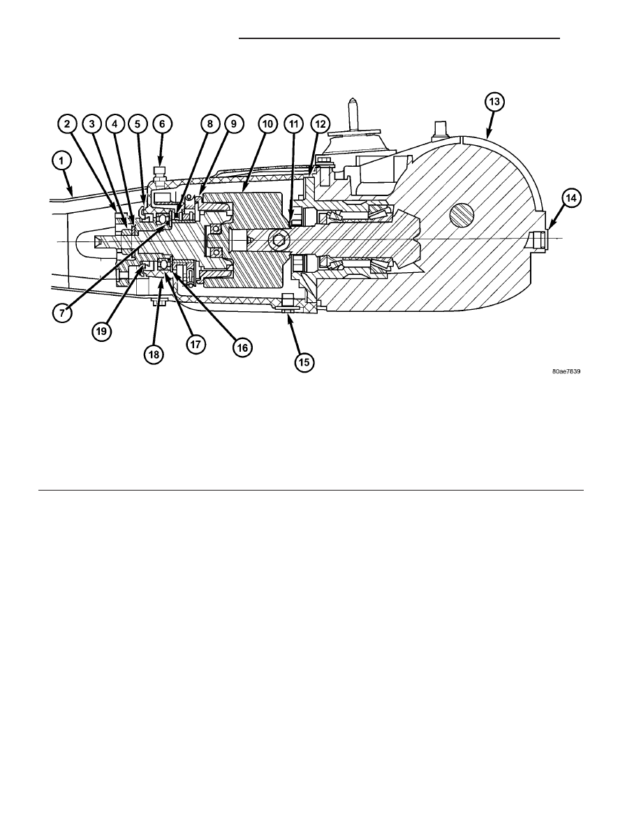
Fig. 1 AWD Driveline Module Assembly

1 - TORQUE ARM

8 - WASHER

15 - PLUG-OVERRUNNING CLUTCH
HOUSING DRAIN

2 - INPUT FLANGE

9 - BI-DIRECTIONAL OVERRUNNING
CLUTCH (BOC)

16 - SNAP RING

3 - FLANGE NUT

10 - VISCOUS COUPLER

17 - BEARING

4 - WASHER

11 - SHIM (SELECT)

18 - OVERRUNING CLUTCH HOUSING

5 - SHIELD

12 - O-RING

19 - SEAL-INPUT FLANGE

6 - VENT

13 - DIFFERENTIAL ASSEMBLY

7 - O-RING

14 - PLUG-DIFFERENTIAL FILL

3a - 12

REAR DRIVELINE MODULE

RG

REAR DRIVELINE MODULE (Continued)

• Engine

• Transmission

• Exhaust

• Propeller shaft (vibration)

• Vehicle body (drumming)
Driveline module noises are normally divided into

two categories: gear noise or bearing noise. A thor-
ough and careful inspection should be completed to
determine the actual source of the noise before
replacing the driveline module.

The rubber mounting bushings help to dampen-out

driveline module noise when properly installed.
Inspect to confirm that no metal contact exists
between the driveline module case and the body. The
complete isolation of noise to one area requires
expertise and experience. Identifying certain types of
vehicle noise baffles even the most capable techni-
cians. Often such practices as:

• Increase tire inflation pressure to eliminate tire

noise.

• Listen for noise at varying speeds with different

driveline load conditions

• Swerving the vehicle from left to right to detect

wheel bearing noise.

All driveline module assemblies produce noise to a

certain extent. Slight carrier noise that is noticeable
only at certain speeds or isolated situations should be
considered normal. Carrier noise tends to peak at a
variety of vehicle speeds. Noise is NOT ALWAYS an
indication of a problem within the carrier.

TIRE NOISE

Tire noise is often mistaken for driveline module

noise. Tires that are unbalanced, worn unevenly or
are worn in a saw-tooth manner are usually noisy.
They often produce a noise that appears to originate
in the driveline module.

Tire noise changes with different road surfaces, but

driveline module noise does not. Inflate all four tires
with approximately 20 psi (138 kPa) more than the
recommended inflation pressure (for test purposes
only). This will alter noise caused by tires, but will
not affect noise caused by the differential. Rear axle
noise usually ceases when coasting at speeds less
than 30 mph (48 km/h); however, tire noise contin-
ues, but at a lower frequency, as the speed is
reduced.

After test has been completed lower tire pressure

back to recommended pressure.

GEAR NOISE (DRIVE PINION AND RING GEAR)

Abnormal gear noise is rare and is usually caused

by scoring on the ring gear and drive pinion. Scoring
is the result of insufficient or incorrect lubricant in
the carrier housing.

Abnormal gear noise can be easily recognized. It

produces a cycling tone that will be very pronounced
within a given speed range. The noise can occur dur-
ing one or more of the following drive conditions:

• Drive

• Road load

• Float

• Coast
Abnormal gear noise usually tends to peak within

a narrow vehicle speed range or ranges. It is usually
more pronounced between 30 to 40 mph (48 to 64
km/h) and 50 to 60 mph (80 to 96 km/h). When objec-
tionable gear noise occurs, note the driving condi-
tions and the speed range.

BEARING NOISE (DRIVE PINION AND
DIFFERENTIAL)

Defective bearings produce a rough growl that is

constant in pitch and varies with the speed of vehi-
cle. Being aware of this will enable a technician to
separate bearing noise from gear noise.

Drive pinion bearing noise that results from defec-

tive or damaged bearings can usually be identified by
its constant, rough sound. Drive pinion front bearing
is usually more pronounced during a coast condition.
Drive pinion rear bearing noise is more pronounced
during a drive condition. The drive pinion bearings
are rotating at a higher rate of speed than either the
differential side bearings or the axle shaft bearing.

Differential side bearing noise will usually produce

a constant, rough sound. The sound is much lower in
frequency than the noise caused by drive pinion bear-
ings.

Bearing noise can best be detected by road testing

the vehicle on a smooth road (black top). However, it
is easy to mistake tire noise for bearing noise. If a
doubt exists, the tire treads should be examined for
irregularities that often causes a noise that resem-
bles bearing noise.

ENGINE AND TRANSMISSION NOISE

Sometimes noise that appears to be in the driv-

eline module assembly is actually caused by the
engine or the transmission. To identify the true
source of the noise, note the approximate vehicle
speed and/or RPM when the noise is most noticeable.
Stop the vehicle next to a flat brick or cement wall
(this will help reflect the sound). Place the transaxle
in NEUTRAL. Accelerate the engine slowly up
through the engine speed that matches the vehicle
speed noted when the noise occurred. If the same
noise is produced, it usually indicates that the noise
is being caused by the engine or transaxle.

RG

REAR DRIVELINE MODULE

3a - 13

REAR DRIVELINE MODULE (Continued)

DIAGNOSIS AND TESTING - REAR DRIVELINE
MODULE OPERATION

Driveline

module

operation

requires

relatively

straight-forward diagnosis. Refer to the following
chart:

DRIVELINE MODULE DIAGNOSIS CHART

CONDITION

POSSIBLE CAUSES

CORRECTION

Rear wheels not
overrunning

1) Bi-directional overrunning clutch
failure

1) Replace overrunning clutch
components as required

No AWD in forward or
reverse directions, propeller
shaft turning

1) Bi-directional overrunning clutch
failure

1) Replace overrunning clutch
components as required

2) Viscous coupling failure

2) Replace viscous coupling

3) Rear differential failure

3) Replace the rear differential
assembly

No AWD in forward or
reverse directions, propeller
shaft not turning

1) Power transfer unit failure.

1) Replace power transfer unit
components as necessary

Vibration at all speeds,
continuous torque transfer

1) Mis-matched tires, worn tires on
front axle.

1) Replace worn or incorrect
(mis-matched) tires with same
make and size

REMOVAL

(1) Raise vehicle on hoist.
(2) Drain fluid from overrunning clutch housing

and/or differential assembly if necessary.

(3) Remove propeller shaft. (Refer to 3 - DIFFER-

ENTIAL

&

DRIVELINE/PROPELLER

SHAFT

-

REMOVAL)

(4) Disconnect left and right rear halfshafts from

output flanges (Fig. 2).

(5) Remove torque arm mount to body bolts.

(6) Position transmission jack to driveline module

assembly and secure assembly to jack.

(7) Remove two driveline module-to-body bolts

(Fig. 3).

(8) Lower

driveline

module

from

vehicle

and

remove from jack.

Fig. 2 Half Shaft Mounting Bolts

1 - SHAFT
2 - FLANGE

Fig. 3 Rear Drive Line Module Assembly Mounting

Bolts

1 - DRIVELINE MODULE RETAINING BOLT (2)
2 - RUBBER ISOLATOR
3 - WASHER

3a - 14

REAR DRIVELINE MODULE

RG

REAR DRIVELINE MODULE (Continued)

DISASSEMBLY

WARNING: Differential is only to be serviced as an
assembly, and no disassembly is required.

(1) Remove

six

torque

arm-to-differential

case

bolts and remove torque arm assembly (Fig. 4).

(2) Remove input flange nut and washer using

Tool 6958 and a breaker bar (Fig. 5).

(3) Remove input flange (Fig. 6).

(4) Remove input flange seal from overrunning

clutch housing using suitable screwdriver (Fig. 7).

Fig. 4 Torque Arm Fasteners

1 - TORQUE ARM ASSEMBLY
2 - BOLT (SIX)

Fig. 5 Input Flange Nut

1 - INPUT FLANGE
2 - TOOL 6958

Fig. 6 Input Flange

1 - INPUT FLANGE/SHIELD

Fig. 7 Input Flange Seal Removal

1 - INPUT FLANGE SEAL
2 - SCREWDRIVER

RG

REAR DRIVELINE MODULE

3a - 15

REAR DRIVELINE MODULE (Continued)


Content   ..  446  447  448  449   ..