Chrysler RG Voyager. Manual - part 353
TEST
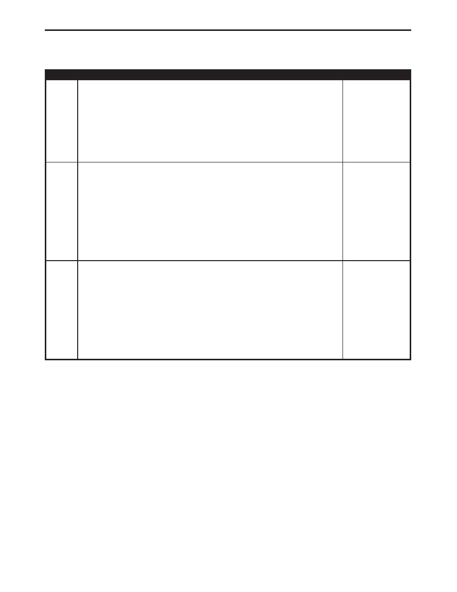
ACTION
APPLICABILITY
4
Turn the ignition off.
Disconnect the CAB harness connector.
Using a 12-volt test light connected to ground, probe the ABS Valve Fused B(+) circuit
at the CAB harness connector.
Did the test light illuminate?
All
Yes
→ Go To 5
No
→ Repair the ABS Valve Fused B(+) circuit for an open.
Perform ABS VERIFICATION TEST - VER 1.
5
Turn the ignition off.
Disconnect the CAB harness connector.
Using a 12-volt test light connected to ground, probe the ABS Pump Fused B(+)
circuit at the CAB harness connector.
Did the test light illuminate?
All
Yes
→ Replace the Controller Antilock Brake in accordance with the
Service Information.
Perform ABS VERIFICATION TEST - VER 1.
No
→ Repair the ABS Pump Fused B(+) circuit for an open.
Perform ABS VERIFICATION TEST - VER 1.
6
Turn the ignition off.
Visually inspect the related wiring harness. Look for any chafed, pierced, pinched, or
partially broken wires.
Visually inspect the related wire harness connectors. Look for broken, bent, pushed
out, or corroded terminals.
Refer to any Hotline letters or Technical Service Bulletins that may apply.
Were any problems found?
All
Yes
→ Repair as necessary.
Perform ABS VERIFICATION TEST - VER 1.
No
→ Test Complete.
13
BRAKES (20E)
CAB INTERNAL FAILURE —
Continued