Chrysler RG Voyager. Manual - part 1091


  Index      Chrysler     Chrysler RG Voyager - service repair manual 2005 year


Search            


Content   ..  1089  1090  1091  1092   ..


Chrysler RG Voyager. Manual - part 1091


ASSEMBLY

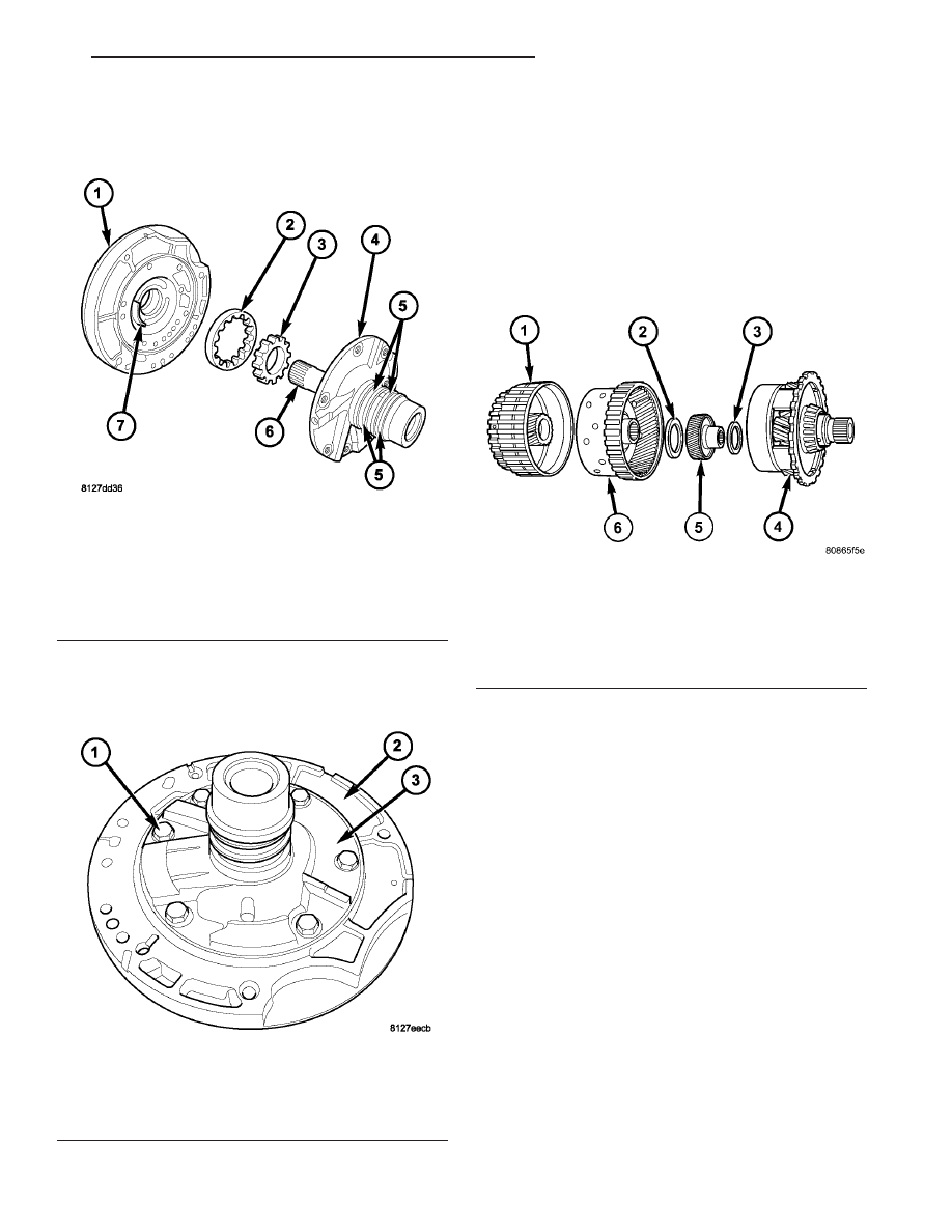
(1) Assemble oil pump as shown in (Fig. 286).

(2) Install and torque reaction shaft support-to-oil

pump housing bolts to 28 N·m (20 ft. lbs.) torque
(Fig. 287).

PLANETARY GEARTRAIN

DESCRIPTION

The planetary geartrain is located between the

input clutch assembly and the rear of the transaxle
case. The planetary geartrain consists of two sun
gears, two planetary carriers, two annulus (ring)
gears, and one output shaft (Fig. 288).

OPERATION

The planetary geartrain utilizes two planetary gear

sets that connect the transmission input shaft to the
output shaft. Input and holding clutches drive or lock
different planetary members to change output ratio
or direction.

Fig. 286 Oil Pump Assembly

1 - PUMP BODY
2 - OUTER GEAR
3 - INNER GEAR
4 - REACTION SHAFT SUPPORT
5 - SEAL RINGS (4)
6 - REACTION SHAFT
7 - CRESCENT

Fig. 287 Reaction Support-to-Pump Body Bolts

1 - BOLT (6)
2 - PUMP BODY
3 - REACTION SHAFT SUPPORT

Fig. 288 Planetary Geartrain

1 - FRONT SUN GEAR ASSEMBLY
2 - #6 THRUST BEARING
3 - #7 THRUST BEARING
4 - REAR CARRIER/FRONT ANNULUS ASSEMBLY
5 - REAR SUN GEAR
6 - FRONT CARRIER/REAR ANNULUS ASSEMBLY

RS

41TE AUTOMATIC TRANSAXLE

21 - 385

OIL PUMP (Continued)

SEALS - OIL PUMP

REMOVAL

(1) Remove transaxle from vehicle (Refer to 21 -

TRANSMISSION/TRANSAXLE/AUTOMATIC - 41TE
- REMOVAL).

(2) Using Tool C-3981-B, remove oil pump seal

(Fig. 289).

INSTALLATION

(1) Using Tool C-4193, install oil pump seal (Fig.

290).

(2) Install transaxle to vehicle (Refer to 21 -

TRANSMISSION/TRANSAXLE/AUTOMATIC - 41TE
- INSTALLATION).

SHIFT INTERLOCK SOLENOID

DESCRIPTION

The Brake/Transmission Shift Interlock system

consists of an electro-magnetic solenoid mounted to
the steering column (Fig. 291). The solenoid’s plunger
consists of an integrated hook, which operates the
shift lever pawl (part of shift lever assembly), and a
plunger return spring (Fig. 292). The solenoid also
has an integrated bracket, which facilitates fastening
to the steering column.

Fig. 289 Remove Oil Pump Seal

1 - TOOL C-3981–B
2 - OIL PUMP SEAL

Fig. 290 Install Oil Pump Seal

1 - TOOL C-4193
2 - HANDLE TOOL C-4171

Fig. 291 Brake/Transmission Shift Interlock (BTSI)

Solenoid Location

1 - BTSI SOLENOID

Fig. 292 Solenoid Plunger and Return Spring

1 - PLUNGER
2 - RETURN SPRING
3 - BTSI SOLENOID

21 - 386

41TE AUTOMATIC TRANSAXLE

RS

OPERATION

The Brake/Transmission Shift Interlock (BTSI)

Solenoid prevents the transmission shift lever from
being moved out of PARK (P) unless the brake pedal
is applied. The BTSI solenoid is hardwired to and
controlled by the Intelligent Power Module (IPM).
Battery voltage is applied to one side of the solenoid
with the ignition key is in either the OFF, ON/RUN,
or START positions (Fig. 293). The ground side of the
solenoid is controlled by a driver within the IPM. It
relies on voltage supplied from the stop lamp switch
to the stop lamp sense circuit within the IPM to tell
when the brake pedal is depressed. When the brake
pedal is depressed, the ground circuit opens, de-ener-
gizing

the

solenoid.

When

the

brake

pedal

is

released, the ground circuit is closed, energizing the
solenoid.

When the ignition key is in either the OFF,

ON/RUN, or START positions, the BTSI solenoid is
energized, and the solenoid plunger hook pulls the
shift lever pawl into position, prohibiting the shift
lever from moving out of PARK (P) (Fig. 294). When
the brake pedal is depressed, the ground circuit
opens, de-energizing the solenoid. This moves the
gearshift lever pawl out of the way (Fig. 295), allow-
ing the shift lever to be moved into any gear position.

A conventional mechanical interlock system is also

used. This system manually prohibits shifter move-
ment when the ignition switch is in the LOCK or
ACC positions. Solenoid operation is not required in
these key positions.

For intended BTSI system operation, refer to the

following chart:

ACTION

EXPECTED RESPONSE

1. Turn key to the

9

OFF

9

position.

1. Shifter CAN be shifted
out of park with brake
pedal applied.

2. Turn key to the

9

ON/RUN

9

position.

2. Shifter CANNOT be
shifted out of park.

3. Turn key to the

9

ON/RUN

9

position and

depress the brake pedal.

3. Shifter CAN be shifted
out of park.

Fig. 293 Ignition Key/Switch Positions

1 - ACC
2 - LOCK
3 - OFF
4 - ON/RUN
5 - START

Fig. 294 Pawl Engaged to Shift Lever

1 - GEAR SHIFT LEVER
2 - GEAR SHIFT LEVER PAWL

Fig. 295 Pawl Disengaged From Shift Lever

1 - GEAR SHIFT LEVER
2 - GEAR SHIFT LEVER PAWL

RS

41TE AUTOMATIC TRANSAXLE

21 - 387

SHIFT INTERLOCK SOLENOID (Continued)

ACTION

EXPECTED RESPONSE

4. Leave shifter in any
gear and try to return key
to the

9

LOCK

9

or

9

ACC

9

position.

4. Key cannot be
returned to the

9

LOCK

9

or

9

ACC

9

position.

5. Return shifter to

9

PARK

9

and try to remove

the key.

5. Key can be removed
(after returning to

9

LOCK

9

position).

6. With the key removed,
try to shift out of

9

PARK

9

.

6. Shifter cannot be
shifted out of

9

PARK

9

.

NOTE: Any failure to meet these expected
responses requires system adjustment or repair.

DIAGNOSIS AND TESTING - BRAKE/
TRANSMISSION SHIFT INTERLOCK SOLENOID

For intended BTSI system operation, refer to the

following chart:

ACTION

EXPECTED RESPONSE

1. Turn key to the

9

OFF

9

position.

1. Shifter CAN be shifted
out of park with brake
pedal applied.

2. Turn key to the

9

ON/RUN

9

position.

2. Shifter CANNOT be
shifted out of park.

3. Turn key to the

9

ON/RUN

9

position and

depress the brake pedal.

3. Shifter CAN be shifted
out of park.

4. Leave shifter in any
gear and try to return key
to the

9

LOCK

9

or

9

ACC

9

position.

4. Key cannot be
returned to the

9

LOCK

9

or

9

ACC

9

position.

5. Return shifter to

9

PARK

9

and try to remove

the key.

5. Key can be removed
(after returning to

9

LOCK

9

position).

6. With the key removed,
try to shift out of

9

PARK

9

.

6. Shifter cannot be
shifted out of

9

PARK

9

.

NOTE: Any failure to meet these expected
responses requires system repair. Refer to the
appropriate Diagnostic Information.

REMOVAL

(1) Disconnect battery negative cable.
(2) Remove instrument panel lower shroud (Fig.

296).

(3) Remove knee bolster (Fig. 297).

(4) Remove steering column lower shroud.
(5) Disconnect brake/transmission shift interlock

(BTSI) solenoid connector (Fig. 298).

Fig. 296 Instrument Panel Lower Silencer

1 - INSTRUMENT PANEL LOWER SILENCER

Fig. 297 Knee Bolster

1 - KNEE BOLSTER

21 - 388

41TE AUTOMATIC TRANSAXLE

RS

SHIFT INTERLOCK SOLENOID (Continued)


Content   ..  1089  1090  1091  1092   ..