Chrysler PT Cruiser. Manual - part 777


  Index      Chrysler     Chrysler PT Cruiser - service repair manual 2005 year


Search            


Content   ..  775  776  777  778   ..


Chrysler PT Cruiser. Manual - part 777


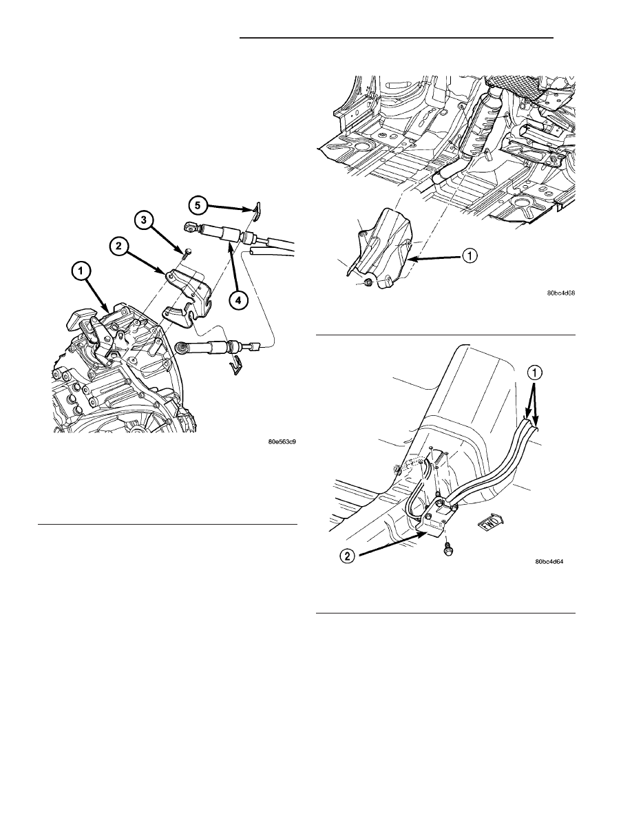
(11) Disconnect cables from the shift levers at the

transaxle (Fig. 151).

CAUTION: Pry up with equal force on both sides of
shifter cable isolator bushings to avoid damaging
cable isolator bushings.

(12) Remove cable retaining clips and remove

cables from bracket (Fig. 151).

(13) Raise vehicle on hoist.
(14) Remove converter heat shield (Fig. 152).
(15) Remove remaining grommet plate-to-floor pan

screw (Fig. 153).

(16) Remove cable assembly from vehicle.

Fig. 151 Gear Shift Cables and Bracket at Transaxle

1 - TRANSAXLE
2 - GEAR SHIFT CABLE BRACKET
3 - BOLT (3)
4 - CABLE ASSEMBLY
5 - RETAINER (2)

Fig. 152 Converter Heat Shield Removal/Installation

1 - CONVERTER HEAT SHIELD

Fig. 153 Shift Cable Assembly at Floor Pan

1 - CABLE ASSEMBLY
2 - GROMMET PLATE

21 - 62

G288 MANUAL TRANSAXLE

PT

GEAR SHIFT CABLE (Continued)

INSTALLATION

CAUTION: Gearshift cable bushings must not be
lubricated or the bushings will swell and split.

(1) Raise vehicle on hoist.
(2) Install cable assembly through floor pan open-

ing and secure to floor pan with grommet plate and
one screw (Fig. 154). Make sure the three grommet
plate studs protrude through cable assembly and
floor pan and tighten screw to 7 N·m (60 in. lbs.).

(3) Route transaxle end of cable assembly into

engine compartment and over transaxle assembly.

(4) Install converter heat shield (Fig. 155).
(5) Lower vehicle.
(6) Install gearshift cables to mounting bracket

and fasten with NEW clips (Fig. 156). Make sure
clips are installed flush to bracket.

(7) Connect gearshift selector and crossover cable

to shift levers at transaxle (Fig. 156).

(8) Install and tighten the three grommet plate-to-

floor pan nuts to 6 N·m (50 in. lbs.) torque.

Fig. 154 Shift Cable Assembly at Floor Pan

1 - CABLE ASSEMBLY
2 - GROMMET PLATE

Fig. 155 Converter Heat Shield Removal/Installation

1 - CONVERTER HEAT SHIELD

Fig. 156 Gear Shift Cables and Bracket at Transaxle

1 - TRANSAXLE
2 - GEAR SHIFT CABLE BRACKET
3 - BOLT (3)
4 - CABLE ASSEMBLY
5 - RETAINER (2)

PT

G288 MANUAL TRANSAXLE

21 - 63

GEAR SHIFT CABLE (Continued)

(9) Install selector cable to shifter lever and secure

cable to shifter bracket. Install clip (Fig. 157).

(10) Install crossover cable to shifter lever and

secure cable to shifter bracket. Install clip (Fig. 158).

NOTE: Only the crossover cable is adjustable. The
selector cable does not have any adjustment capa-
bilities.

(11) Adjust crossover cable as follows:

(a) Loosen adjusting screw on crossover cable at

shifter (Fig. 159).

(b) The

gearshift

mechanism

and

transaxle

crossover lever are spring-loaded and self-center-
ing. Alignment pins used in the past are not
required anymore. Allow gearshift mechanism and
transaxle crossover lever to relax in their neutral
positions. To ensure the gearshift lever is in the
proper position, place the shifter in 3rd or 4th gear
if necessary. Torque adjustment screw to 8 N·m (70
in. lbs.). Care must be taken to avoid moving the
shift mechanism off-center during screw tighten-
ing.

(c) Perform functional check by shifting trans-

axle into all gears.

(12) Install center console assembly (Fig. 160). Ver-

ify that boot is not pinched at console opening before
tightening.

(13) Position gearshift boot (Fig. 161) over the

gearshift mechanism and engage tab on mount ring
at front to opening in console. Apply hand pressure to
engage bosses on mount ring of boot to console open-
ing slots.

Fig. 157 Selector Cable at Shifter Assembly

1 - SHIFTER
2 - CLIP
3 - SELECTOR CABLE

Fig. 158 Crossover Cable at Shifter Assembly

1 - GROMMET PLATE NUT
2 - SHIFTER
3 - CROSSOVER CABLE
4 - CLIP

Fig. 159 Crossover Cable Adjustment Screw

1 - CROSSOVER ADJUSTMENT SCREW

21 - 64

G288 MANUAL TRANSAXLE

PT

GEAR SHIFT CABLE (Continued)

(14) Position gearshift knob hole over the gearshift

mechanism (Fig. 162) and align the shift pattern.

(15) Strike knob with rubber mallet to engage

knob to mechanism.

(16) Verify that shift pattern is aligned properly.
(17) Install battery tray (Fig. 163).

Fig. 160 Center Console Removal/Installation -

Typical

1 - CENTER CONSOLE

Fig. 161 Gearshift Boot

1 - GEARSHIFT BOOT

Fig. 162 Gearshift Knob Removal/Installation

1 - GEARSHIFT KNOB

Fig. 163 Battery Tray Removal/Installation

1 - BATTERY TRAY

PT

G288 MANUAL TRANSAXLE

21 - 65

GEAR SHIFT CABLE (Continued)


Content   ..  775  776  777  778   ..