Chrysler PT Cruiser. Manual - part 740


  Index      Chrysler     Chrysler PT Cruiser - service repair manual 2005 year


Search            


Content   ..  738  739  740  741   ..


Chrysler PT Cruiser. Manual - part 740


A ground for the sensor is provided through the sen-
sor return circuit. The input to the PCM occurs on a
5 volt output reference circuit that operates as fol-
lows: The Hall-effect sensor contains a powerful mag-
net. As the magnetic field passes over the dense
portion of the counterweight, the 5-volt signal is
pulled to ground (.3 volts) through a transistor in the
sensor. When the magnetic field passes over the
notches in the crankshaft counterwieght, the mag-
netic field turns off the transistor in the sensor, caus-

ing the PCM to register the 5-volt signal. The PCM
identifies crankshaft position by registering the
change from 5 to 0 volts, as signaled from the Crank-
shaft Position sensor.

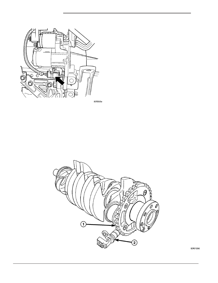
The PCM determines what cylinder to fire from the

crankshaft position sensor (Fig. 6) input and the
camshaft position sensor input. The #8 crankshaft
counterweight has a target ring with 32 teeth and
notches, including one long referance tooth and
notch. From the crankshaft position sensor input the
PCM determines engine speed and crankshaft angle
(position).

REMOVAL

REMOVAL - 1.6L

(1) Disconnect the negative battery cable
(2) Raise vehicle and support.
(3) Disconnect the electrical connector (Fig. 7).
(4) Remove bolt from Crankshaft sensor.
(5) Remove sensor (Fig. 8).

REMOVAL - 2.0, 2.4, 2.4L TURBO

The Crankshaft Position Sensor is in the front of

the engine block just under the starter motor (Fig. 9).

(1) Disconnect the negative battery cable.
(2) Raise vehicle and support.
(3) On 2.4L SRT-4 remove the lower inner cooler

hose from the metal tube.

Fig. 6 TIMING REFERENCE NOTCHES (NGC)

1 - Crankshaft

2 - Crankshaft Position Sensor

Fig. 5 Crankshaft Position Sensor

14 - 28

FUEL INJECTION

PT

CRANKSHAFT POSITION SENSOR (Continued)

(4) Remove the Structural Collar (Fig. 10), refer to

the Engine, Structural Collar Removal and Installa-
tion section.

(5) Unlock and disconnect the electrical connector

to the crankshaft position sensor.

(6) Remove the crankshaft position sensor bolt.
(7) Remove the sensor (Fig. 11).

INSTALLATION

INSTALLATION - 1.6L

(1) Install the Crankshaft sensor (Fig. 7).
(2) Install bolt and tighten to 10 N·m (90 in. lbs.).
(3) Connect the electrical connector (Fig. 8).

(4) Lower vehicle.
(5) Connect the negative battery cable.

INSTALLATION - 2.0, 2.4, 2.4L Turbo

(1) Check o-ring for damage and lubricate the

o-ring with engine oil before installing sensor (Fig.
11).

(2) Use a twisting motion when installing the sen-

sor.

(3) Install and tighten the crankshaft position sen-

sor bolt and tighten to 9 N·m (80 ±15 in. lbs.).

(4) Connect and lock the electrical connector to the

crankshaft position sensor.

Fig. 7 CRANKSHAFT SENSOR LOCATION

Fig. 8 CRANKSHAFT POSITION SENSOR

Fig. 9 CRANKSHAFT POSITION SENSOR LOCATION

Fig. 10 Structural Collar and Bending Strut—

(Automatic Transaxle Equipped)

1–8 – BOLT TIGHTENING SEQUENCE
9 – TRANSAXLE
10 – COLLAR
11 – OIL PAN
12 – STRUT

PT

FUEL INJECTION

14 - 29

CRANKSHAFT POSITION SENSOR (Continued)

(5) Install the Structural Collar, refer to the

Engine, Structural Collar Removal and Installation
section (Fig. 10).

(6) On 2.4L SRT-4 install the lower inner cooler

hose to metal tube and tighten clamp.

(7) Lower vehicle.
(8) Connect the negative battery cable.

FUEL INJECTOR

DESCRIPTION

The injectors are positioned in the intake manifold

with the nozzle ends directly above the intake valve
port (Fig. 12).

OPERATION

The fuel injectors are 12 volt electrical solenoids

(Fig. 13). The injector contains a pintle that closes off
an orifice at the nozzle end. When electric current is
supplied to the injector, the armature and needle
move a short distance against a spring, allowing fuel
to flow out the orifice. Because the fuel is under high
pressure, a fine spray is developed in the shape of a
hollow cone or two streams. The spraying action
atomizes the fuel, adding it to the air entering the
combustion chamber. Fuel injectors are not inter-
changeable between engines.

The PCM provides battery voltage to each injector

through the ASD relay. Injector operation is con-
trolled by a ground path provided for each injector by
the PCM. Injector on-time (pulse-width) is variable,
and is determined by the PCM processing all the
data previously discussed to obtain the optimum
injector pulse width for each operating condition. The
pulse width is controlled by the duration of the
ground path provided.

Fig. 11 CRANKSHAFT POSITION SENSOR - 2.4 L TURBO

Fig. 12 Fuel Injector Location—Typical

1 - FUEL INJECTOR
2 - FUEL TEST PORT

Fig. 13 FUEL INJECTOR - TYPICAL

1 - FUEL INJECTOR
2 - NOZZLE
3 - TOP (FUEL ENTRY)

14 - 30

FUEL INJECTION

PT

CRANKSHAFT POSITION SENSOR (Continued)

STANDARD PROCEDURE

REMOVAL - INJECTOR CONNECTOR

(1) Disconnect electrical connectors at the fuel

injectors (Fig. 14). To remove connector refer to (Fig.
15). Pull the red colored slider away from injector (1).
While pulling the slider, depress tab (2) and remove
connector (3) from injector. The factory fuel injection
wiring harness is numerically tagged (INJ 1, INJ 2,
etc.) for injector position identification. If harness is
not tagged, make note of wiring location before
removal.

REMOVAL

REMOVAL - 2.0, 2.4L

WARNING: RELEASE FUEL SYSTEM PRESSURE
BEFORE SERVICING FUEL SYSTEM COMPONENTS.
SERVICE VEHICLES IN WELL VENTILATED AREAS
AND AVOID IGNITION SOURCES. NEVER SMOKE
WHILE

SERVICING

THE

VEHICLE.

THIS

MAY

RESULT IN PERSONAL INJURY OR DEATH.

(1) Release fuel system pressure. Refer to Fuel

System Pressure Release procedure in this section.

(2) Remove the air cleaner lid, disconnect the inlet

air temperature sensor and makeup air hose.

(3) Remove the negative battery cable.
(4) Remove the engine cover or throttle control

shield if equipped.

NOTE: WRAP SHOP TOWELS AROUND HOSE TO
CATCH ANY GASOLINE SPILLAGE.

(5) Disconnect fuel supply tube from rail. Refer to

Quick-Connect Fittings in this section.

(6) Remove the Intake Manifold, refer to the

Engine section.

(7) Disconnect electrical connectors from fuel injec-

tors.

(8) Remove bolts holding fuel rail (Fig. 16).
(9) Remove the fuel rail and injectors.
(10) Remove injectors from the fuel rail.

REMOVAL - 1.6L

WARNING: RELEASE FUEL SYSTEM PRESSURE
BEFORE SERVICING FUEL SYSTEM COMPONENTS.
SERVICE VEHICLES IN WELL VENTILATED AREAS
AND AVOID IGNITION SOURCES. NEVER SMOKE
WHILE

SERVICING

THE

VEHICLE.

THIS

MAY

RESULT IN PERSONAL INJURY OR DEATH.

(1) Release the fuel pressure, refer to the fuel

pressure release procedure.

(2) Remove air cleaner assembly cover.
(3) Disconnect the negative battery cable.

Fig. 14 Fuel Injectors

Fig. 15 Remove/Install Injector Connector

PT

FUEL INJECTION

14 - 31

FUEL INJECTOR (Continued)


Content   ..  738  739  740  741   ..