Chrysler Pacifica. Manual - part 899


  Index      Chrysler     Chrysler Pacifica - service repair manual 2005 year


Search            


Content   ..  897  898  899  900   ..


Chrysler Pacifica. Manual - part 899


(13) Remove the two screws that secure the A/C

expansion valve to the evaporator tube tapping plate
and remove the expansion valve.

(14) Remove the seals from the evaporator inlet

and outlet tube fittings and discard.

(15) Install plugs in, or tape over the opened evap-

orator inlet and outlet tube fittings and both expan-
sion valve ports.

(16) Remove the retaining screw and evaporator

temperature sensor from the A/C expansion valve, if
required (Refer to 24 - HEATING & AIR CONDI-
TIONING/CONTROLS

-

FRONT/EVAPORATOR

TEMPERATURE SENSOR - REMOVAL).

INSTALLATION

NOTE: Any grease removed with the evaporator
temperature sensor must be replaced. Failure to do
so could result in poor A/C performance.

(1) If removed, install the evaporator temperature

sensor and retaining screw onto the A/C expansion
valve (Refer to 24 - HEATING & AIR CONDITION-
ING/CONTROLS - FRONT/EVAPORATOR TEMPER-
ATURE SENSOR - INSTALLATION).

(2) Remove the tape or plugs from the evaporator

inlet and outlet tube fittings and both ports on the
back of the A/C expansion valve.

(3) Lubricate new rubber O-ring seals with clean

refrigerant oil and install them on the evaporator
inlet and outlet tube fittings.

(4) Position the A/C expansion valve onto the evap-

orator inlet and outlet tube fittings.

(5) Install the two screws that secure the A/C

expansion valve to the evaporator tube tapping plate
plate. Tighten the screws to 11 N·m (97 in. lbs.).

(6) Connect the HVAC wire harness connector to

the evaporator temperature sensor.

(7) Remove the tape or plugs from the front liquid

line rear section and suction line fittings for the
expansion valve and both ports on the front of the
expansion valve.

(8) Lubricate new rubber O-ring seals with clean

refrigerant oil and install them on the front liquid
line rear section and suction line fittings for the
expansion valve.

(9) Connect the A/C liquid and suction lines to the

expansion valve.

(10) Install the nut that secures the A/C liquid and

suction lines to the expansion valve. Tighten the nut
to 23 N·m (17 ft. lbs.).

(11) Remove the tape or plugs from the liquid line

rear section fitting and the receiver/drier outlet port.

(12) Lubricate a new rubber O-ring seal with clean

refrigerant oil and install it on the liquid line fitting.

(13) Connect the liquid line fitting to the receiver/

drier outlet port.

(14) Install the screw that secures the liquid line

fitting to the receiver/drier. Tighten the screw to 11
N·m (97 in. lbs.).

(15) Connect the wire harness connector to the A/C

pressure transducer.

(16) Install the drain tube to the wiper module.
(17) Install the air cleaner housing and air inlet

tube (Refer to 9 - ENGINE/AIR INTAKE SYSTEM/
AIR CLEANER HOUSING - INSTALLATION).

(18) Reconnect the negative battery cable.
(19) Evacuate the refrigerant system (Refer to 24 -

HEATING & AIR CONDITIONING/PLUMBING -
STANDARD PROCEDURE - REFRIGERANT SYS-
TEM EVACUATE).

(20) Charge the refrigerant system (Refer to 24 -

HEATING & AIR CONDITIONING/PLUMBING -
STANDARD PROCEDURE - REFRIGERANT SYS-
TEM CHARGE).

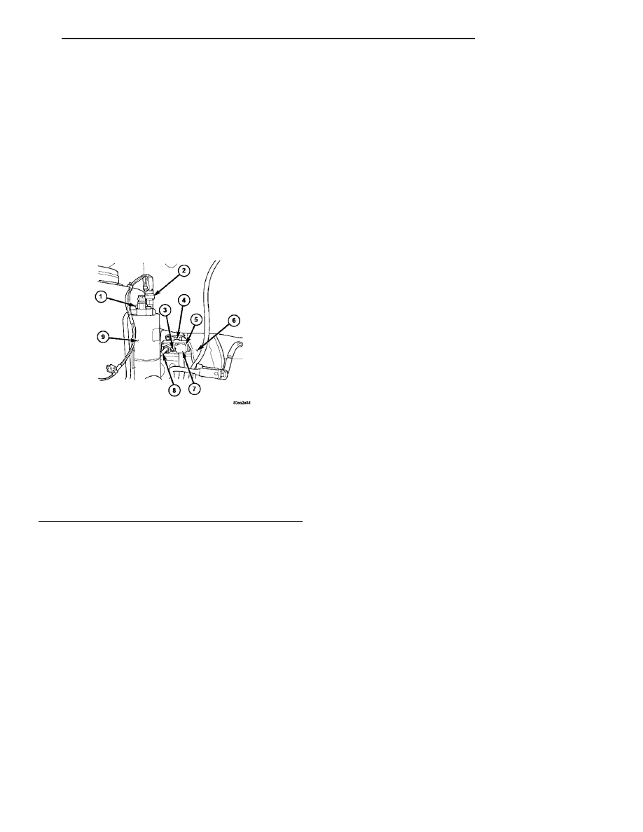
Fig. 16 A/C Expansion Valve

1 - LIQUID LINE FITTING BOLT
2 - A/C PRESSURE TRANSDUCER
3 - NUT
4 - EVAPORATOR TEMPERATURE SENSOR
5 - A/C EXPANSION VALVE
6 - DRAIN TUBE
7 - A/C SUCTION LINE
8 - A/C LIQUID LINE (REAR SECTION)
9 - RECEIVER/DRIER

CS

PLUMBING

24 - 73

EXPANSION VALVE (Continued)

HEATER CORE

DESCRIPTION

The heater core (Fig. 17) is mounted into the

HVAC air distribution housing, located behind the
instrument

panel.

The

heater

core

is

a

heat

exchanger made of rows of tubes and fins. The heater
core tubes are attached to the heater core by a seal-
ing plate and bolt.

The heater core can be serviced without removing

the air distribution housing from the vehicle.

OPERATION

Engine coolant is circulated through the heater hoses

to the heater core at all times. As the coolant flows
through the heater core, heat is removed from the
engine and is transferred to the heater core tubes and
fins. Air directed through the heater core picks up the
heat from the heater core fins. The blend-air door(s)
allows control of the heater output air temperature by
regulating the amount of air flowing through the heater
core. The blower motor speed controls the volume of air
flowing through the HVAC housing.

The heater core cannot be repaired and, if faulty or

damaged, it must be replaced.

REMOVAL

HEATER CORE TUBES

WARNING: On vehicles equipped with airbags, dis-
able the airbag system before attempting any steer-
ing wheel, steering column, or instrument panel
component diagnosis or service. Disconnect and
isolate the battery negative (ground) cable, then
wait two minutes for the airbag system capacitor to
discharge before performing further diagnosis or
service. This is the only sure way to disable the air-
bag system. Failure to take the proper precautions
could result in accidental airbag deployment and
possible personal injury or death.

WARNING: Refer to the applicable warnings and
cautions for this system before performing the fol-
lowing operation (Refer to 24 - HEATING & AIR
CONDITIONING/PLUMBING - WARNINGS) and (Refer
to 24 - HEATING & AIR CONDITIONING/PLUMBING -
CAUTIONS). Failure to follow the warnings and cau-
tions could result in possible personal injury or
death.

(1) Drain the engine cooling system (Refer to 7 -

COOLING - STANDARD PROCEDURE - COOLING
SYSTEM DRAIN).

(2) Disconnect and isolate the negative battery

cable.

(3) Disconnect the heater hoses from the heater

core tubes (Refer to 24 - HEATING & AIR CONDI-
TIONING/PLUMBING/HEATER

INLET

HOSE

-

REMOVAL) and (Refer to 24 - HEATING & AIR
CONDITIONING/PLUMBING/HEATER

RETURN

HOSE - REMOVAL).

(4) Remove the silencer from beneath the driver

side end of the instrument panel.

NOTE: Take the proper precautions to protect the
carpeting below the heater core from spilled engine
coolant and have absorbent toweling readily avail-
able to clean up any spills.

(5) Remove the bolt that secures the heater core

tube sealing plate to the heater core (Fig. 18).

(6) Push both heater core tubes simultaneously

toward the dash panel to disengage the tubes from
the heater core and remove and discard the O-ring
seals.

(7) Install plugs in, or tape over the opened heater

core tube fittings and both heater core ports.

(8) Pull both heater core tubes simultaneously

away from the distribution housing and rearward to
disengage tubes from the dash panel seal and remove
the tubes.

Fig. 17 Heater Core

1 - HEATER CORE
2 - HEATER CORE TUBES
3 - SEALING PLATE
4 - BOLT

24 - 74

PLUMBING

CS

HEATER CORE

WARNING: On vehicles equipped with airbags, dis-
able the airbag system before attempting any steer-
ing wheel, steering column, or instrument panel
component diagnosis or service. Disconnect and
isolate the battery negative (ground) cable, then
wait two minutes for the airbag system capacitor to
discharge before performing further diagnosis or
service. This is the only sure way to disable the air-
bag system. Failure to take the proper precautions
could result in accidental airbag deployment and
possible personal injury or death.

WARNING: Refer to the applicable warnings and
cautions for this system before performing the fol-
lowing operation (Refer to 24 - HEATING & AIR
CONDITIONING/PLUMBING - WARNINGS) and (Refer
to 24 - HEATING & AIR CONDITIONING/PLUMBING -
CAUTIONS). Failure to follow the warnings and cau-
tions could result in possible personal injury or
death.

(1) Remove the silencer boot fasteners located

around the base of the lower steering shaft from the
dash panel so that it may be pushed aside.

(2) Remove the brake lamp switch from its mount-

ing bracket (Refer to 8 - ELECTRICAL/LAMPS/
LIGHTING - EXTERIOR/BRAKE LAMP SWITCH -
REMOVAL).

(3) Disconnect the power brake booster input rod

(push rod) from the pin on the brake pedal arm
(Refer to 5 - BRAKES - ABS/HYDRAULIC/ME-

CHANICAL/POWER

BRAKE

BOOSTER

-

REMOVAL).

NOTE: Take the proper precautions to protect the
carpeting below the heater core from spilled engine
coolant and have absorbent toweling readily avail-
able to clean up any spills.

(4) Remove the heater core tubes (Refer to 24 -

HEATING

&

AIR

CONDITIONING/PLUMBING/

HEATER

CORE

-

HEATER

CORE

TUBES

-

REMOVAL).

(5) Remove the two screws that secure the heater

core mounting plate to the HVAC air distribution
housing.

(6) While pulling the accelerator pedal upward

(Fig. 19) and pushing the brake pedal downward
(Fig. 20) for clearance, remove the heater core from
the air distribution housing.

INSTALLATION

HEATER CORE TUBES

(1) Remove the plugs or tape from both heater core

tube fittings and both heater core ports.

(2) Lubricate new rubber O-ring seals with clean

engine coolant and install them onto the heater core
tube fittings. Use only the specified O-ring as they
are made of a special material for the engine cooling
system.

(3) Position the heater core tubes and sealing plate

to the dash panel, below the instrument panel.

(4) Install both heater core tubes simultaneously

through the dash panel seal.

(5) Position both heater core tubes and the sealing

plate simultaneously onto the heater core.

Fig. 18 Heater Core Tubes

1 - SEAL
2 - HEATER CORE TUBES
3 - SCREW
4 - HEATER CORE
5 - DISTRIBUTION HOUSING
6 - SEALING PLATE

Fig. 19 Accelerator Pedal

1 - HEATER CORE

CS

PLUMBING

24 - 75

HEATER CORE (Continued)

NOTE: The heater core tubes each have a slot that
must be indexed to a location tab within each of the
heater core ports. Adjust the position of the tubes
as required so that the sealing plate fits flush
against the heater core supply and return ports,
which indicates that the tubes are properly indexed.

(6) Index both heater core tubes to the heater core

ports.

(7) Install the bolt that secures the heater core

tube sealing plate to the heater core. Tighten the bolt
to 3 N·m (27 in. lbs.).

(8) Install the silencer under the driver side end of

the instrument panel.

(9) Connect the heater hoses to the heater hose

tubes (Refer to 24 - HEATING & AIR CONDITION-
ING/PLUMBING/HEATER INLET HOSE - INSTAL-
LATION) and (Refer to 24 - HEATING & AIR
CONDITIONING/PLUMBING/HEATER

RETURN

HOSE - INSTALLATION).

(10) Reconnect the negative battery cable.
(11) Refill the engine cooling system (Refer to 7 -

COOLING - STANDARD PROCEDURE - COOLING
SYSTEM REFILL).

HEATER CORE

(1) While pushing the brake pedal downward and

pulling the accelerator pedal upward for clearance,
install the heater core into the HVAC air distribution
housing.

(2) Install the two screws that secure the heater

core to the air distribution housing. Tighten the
screws to 2 N·m (17 in. lbs.).

(3) Install the heater core tubes (Refer to 24 -

HEATING

&

AIR

CONDITIONING/PLUMBING/

HEATER CORE - INSTALLATION).

(4) Connect the power brake booster input rod

(push rod) to the pin on the brake pedal arm (Refer
to

5

-

BRAKES/HYDRAULIC/MECHANICAL/

POWER BRAKE BOOSTER - INSTALLATION).

(5) Install the brake lamp switch into its mounting

bracket (Refer to 8 - ELECTRICAL/LAMPS/LIGHT-
ING

-

EXTERIOR/BRAKE

LAMP

SWITCH

-

INSTALLATION).

(6) Install the silencer boot around the base of the

lower steering shaft on the dash panel.

(7) Reconnect the negative battery cable.
(8) If the heater core is being replaced, flush the

cooling system (Refer to 7 - COOLING - STANDARD
PROCEDURE - COOLING SYSTEM CLEANING/
REVERSE FLUSHING).

(9) Refill the engine cooling system (Refer to 7 -

COOLING - STANDARD PROCEDURE - COOLING
SYSTEM REFILL).

HEATER INLET HOSE

REMOVAL

WARNING: Refer to the applicable warnings and
cautions for this system before performing the fol-
lowing operation (Refer to 24 - HEATING & AIR
CONDITIONING/PLUMBING - WARNINGS) and (Refer
to 24 - HEATING & AIR CONDITIONING/PLUMBING -
CAUTIONS). Failure to follow the warnings and cau-
tions could result in possible personal injury or
death.

NOTE: The heater inlet hose is constructed from
formed steel tubing and rubber hoses. Depending
on application, the ends are secured to the heater
core, engine oil cooler or the engine by spring ten-
sion clamps.

(1) Drain the engine cooling system (Refer to 7 -

COOLING - STANDARD PROCEDURE - COOLING
SYSTEM DRAIN).

(2) Using spring tension clamp pliers, compress

and slide the clamps off of each end of the hose being
removed (Fig. 21).

CAUTION: DO NOT apply excessive pressure on
heater tubes or connections when removing heater
hoses. Excessive pressure may damage or deform
the tubes/heater core, causing an engine coolant
leak.

(3) Disconnect each hose end by carefully twisting

the hose back and forth on the tube, while gently
pulling it away from the end of the tube.

Fig. 20 Brake Pedal

1 - HEATER CORE
2 - BRAKE PEDAL

24 - 76

PLUMBING

CS

HEATER CORE (Continued)


Content   ..  897  898  899  900   ..