Chrysler Pacifica. Manual - part 838


  Index      Chrysler     Chrysler Pacifica - service repair manual 2005 year


Search            


Content   ..  836  837  838  839   ..


Chrysler Pacifica. Manual - part 838


(9) Remove seat cushion cover and foam pad from

the seat pan (Fig. 85) and (Fig. 86).

(10) Remove one screw (at the rear of the cushion

pan) attaching the cushion slider (Fig. 87).

(11) Remove cushion slider.

INSTALLATION

(1) Place cushion slider into position (Fig. 87).
(2) Install cushion attaching screw to cushion pan.
(3) Install seat cushion cover and foam pad onto

seat pan (Fig. 85) and (Fig. 86).

(4) Engage J-straps (Fig. 84).
(5) Install cushion assembly onto the seat risers.
(6) Install cushion assembly by sliding the front

links onto the riser pins and twisting the cushion
assembly to engage the rear sliders onto the riser
tracks (Fig. 83).

(7) Install two bolts attaching front cushion pan to

link and risers (Fig. 81). Tighten to 29 N·m (21 ft.
lbs.) torque.

(8) Install drive link assembly.
(9) Install two bolts attaching drive link assembly

(Fig. 81). Tighten to 10 N·m (7 ft. lbs.) torque.

(10) Install third row seat. (Refer to 23 - BODY/

SEATS/THIRD ROW SEAT - INSTALLATION).

(11) Install rear floor stowage bin. (Refer to 23 -

BODY/INTERIOR/REAR FLOOR STOWAGE TRAY -
INSTALLATION).

(12) Close liftgate.

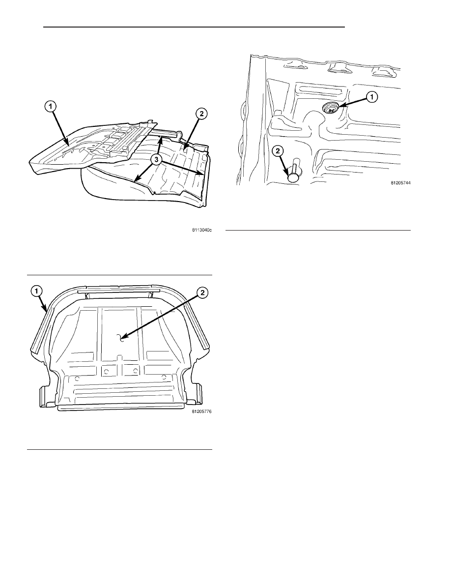
Fig. 85 THIRD ROW SEAT CUSHION

1 - SEAT CUSHION PAN
2 - SEAT CUSHION FOAM AND COVER
3 - J-STRAPS

Fig. 86 THIRD ROW SEAT CUSHION FOAM PAD

1 - SEAT CUSHION COVER
2 - SEAT CUSHION FOAM PAD

Fig. 87 THIRD ROW SEAT SLIDER ATTACHING

SCREW

1 - ATTACHING SCREW
2 - SLIDER GUIDE PIN

CS

SEATS

23 - 147

THIRD ROW CUSHION SLIDER (Continued)

THIRD ROW OUTBOARD
LATCH ASSEMBLY

REMOVAL

(1) Open liftgate.
(2) Remove rear floor stowage bin. (Refer to 23 -

BODY/INTERIOR/REAR FLOOR STOWAGE BIN -
REMOVAL).

(3) Remove third row seat. (Refer to 23 - BODY/

SEATS/THIRD ROW SEAT - REMOVAL).

(4) Remove two bolts (on outboard side of seat)

attaching drive link assembly (Fig. 88).

(5) Remove drive link assembly.
(6) Remove outboard seat back shield (Fig. 89).

(7) Disconnect fold flat cable from outboard fold

flat mechanism (Fig. 90).

(8) Remove two bolts attaching outboard fold flat

mechanism to outer seat back. Remove two nuts
attaching outboard fold flat mechanism to outboard
riser (Fig. 91).

(9) Remove outboard fold flat mechanism.

INSTALLATION

(1) Place outboard fold flat mechanism into posi-

tion.

(2) Install two bolts attaching outboard fold flat

mechanism to outer seat back. Install two nuts
attaching outboard fold flat mechanism to outboard
riser (Fig. 91).

(3) Connect fold flat cable to outboard fold flat

mechanism (Fig. 90).

(4) Install outboard seat back shield (Fig. 89).
(5) Place drive link assembly into position.

Fig. 88 DRIVE LINK AND SHIELD

1 - DRIVE LINK AND SHIELD

Fig. 89 OUTBOARD SEAT BACK SHIELD

1 - SHIELD

Fig. 90 FOLD FLAT CABLE ATTACHING POINTS

1 - FOLD FLAT MECHANISM
2 - FOLD FLAT CABLE ATTACHING POINTS

Fig. 91 FOLD FLAT MECHANISM

1 - FOLD FLAT MECHANISM

23 - 148

SEATS

CS

(6) Install two bolts (on outboard side of seat)

attaching drive link assembly (Fig. 88). Tighten to 10
N·m (7 ft. lbs.) torque.

(7) Install third row seat. (Refer to 23 - BODY/

SEATS/THIRD ROW SEAT - INSTALLATION).

(8) Install rear floor stowage bin. (Refer to 23 -

BODY/INTERIOR/REAR FLOOR STOWAGE TRAY -
INSTALLATION).

(9) Close liftgate.

THIRD ROW INBOARD PIVOT

REMOVAL

(1) Open liftgate.
(2) Remove rear floor stowage bin. (Refer to 23 -

BODY/INTERIOR/REAR FLOOR STOWAGE BIN -
REMOVAL).

(3) Remove third row seat. (Refer to 23 - BODY/

SEATS/THIRD ROW SEAT - REMOVAL).

(4) Using finger, disengage fold flat cable from

handle (Fig. 92).

(5) Release tab attaching fold flat handle to load

floor panel (Fig. 93).

(6) Disconnect fold flat cable from handle and

remove handle.

(7) Remove load floor panel by using a trim tool

and lifting up the edges to disengage the push pins
(Fig. 94).

Fig. 92 FOLD FLAT CABLE

1 - RELEASE CABLE

Fig. 93 REMOVE FOLD FLAT HANDLE

1 - PRY TAB INWARD
2 - TRIM TOOL

Fig. 94 REMOVE LOAD FLOOR PANEL

1 - TRIM TOOL
2 - LOAD FLOOR PANEL

CS

SEATS

23 - 149

THIRD ROW OUTBOARD LATCH ASSEMBLY (Continued)

(8) Remove inboard pivot drive shield screw (Fig.

95).

(9) Disengage J-straps to uncover inboard pivot

(Fig. 96).

(10) Remove two bolts attaching inboard free pivot

to inner seat back. Remove two nuts attaching
inboard free pivot to inboard riser

(11) Remove inboard free pivot assembly.

INSTALLATION

(1) Place inboard free pivot assembly into position

(Fig. 92).

(2) Install two bolts attaching inboard free pivot to

inner seat back. Install two nuts attaching inboard
free pivot to inboard riser.

(3) Engage seat cover J-straps.
(4) Install inboard pivot drive shield (Fig. 93).

(5) Align load floor panel and push pins fasteners

with holes in seat frame and press into position (Fig.
92).

(6) Connect fold flat cable to handle and press

handle into position on load floor panel.

(7) Install third row seat. (Refer to 23 - BODY/

SEATS/THIRD ROW SEAT - INSTALLATION).

(8) Install rear floor stowage bin. (Refer to 23 -

BODY/INTERIOR/REAR FLOOR STOWAGE TRAY -
INSTALLATION).

THIRD ROW OUTBOARD
LINK/SHIELD

REMOVAL

(1) Open liftgate.
(2) Remove rear floor stowage bin. (Refer to 23 -

BODY/INTERIOR/REAR FLOOR STOWAGE BIN -
REMOVAL).

(3) Remove third row seat. (Refer to 23 - BODY/

SEATS/THIRD ROW SEAT - REMOVAL).

(4) Remove two bolts (on outboard side of seat)

attaching drive link assembly (Fig. 97).

(5) Remove drive link and shield assembly.

INSTALLATION

(1) Place drive link/shield assembly into position.
(2) Install two bolts (on outboard side of seat)

attaching drive link assembly (Fig. 58). Tighten to 10
N·m (7 ft. lbs.) torque.

(3) Install third row seat. (Refer to 23 - BODY/

SEATS/THIRD ROW SEAT - INSTALLATION).

(4) Install rear floor stowage bin. (Refer to 23 -

BODY/INTERIOR/REAR FLOOR STOWAGE TRAY -
INSTALLATION).

(5) Close liftgate.

Fig. 95 INBOARD PIVOT DRIVE SHIELD

1 - SHIELD

Fig. 96 FREE PIVOT ASSEMBLY

1 - INBOARD FREE PIVOT

Fig. 97 DRIVE LINK AND SHIELD

1 - DRIVE LINK AND SHIELD

23 - 150

SEATS

CS

THIRD ROW INBOARD PIVOT (Continued)


Content   ..  836  837  838  839   ..