Chrysler Pacifica. Manual - part 827


  Index      Chrysler     Chrysler Pacifica - service repair manual 2005 year


Search            


Content   ..  825  826  827  828   ..


Chrysler Pacifica. Manual - part 827


REAR HEADER TRIM

REMOVAL

(1) Disengage locking tabs attaching rear header

trim panel (Fig. 27).

(2) Remove rear header trim from vehicle.

INSTALLATION

(1) Place rear header trim panel into position (Fig.

27).

(2) Press on rear header trim to engage push pins

to body assembly.

REAR VIEW MIRROR

REMOVAL

(1) If equipped, disconnect mirror wire connector(s)

(Fig. 28).

(2) Loosen the mirror base set screw.
(3) Slide the mirror base upward and off the sup-

port button.

INSTALLATION

(1) Position the mirror base at the support button

and slide it downward onto the button (Fig. 28).

(2) Tighten the set screw 1 N·m (15 in. lbs.)

torque.

(3) If equipped, connect mirror wire connector(s).

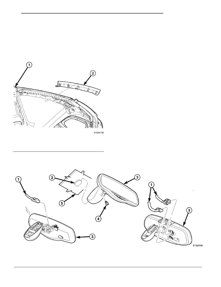
Fig. 28 REAR VIEW MIRROR

1 - MIRROR WIRE CONNECTOR(s)
2 - MIRROR SUPPORT BUTTON
3 - REAR VIEW MIRROR

4 - SET SCREW
5 - WINDSHIELD

Fig. 27 REAR HEADER TRIM PANEL

1 - BODY ASSEMBLY
2 - REAR HEADER TRIM PANEL

CS

INTERIOR

23 - 103

SHIFTER BEZEL

REMOVAL

(1) Remove shifter knob. (Refer to 21 - TRANS-

MISSION/TRANSAXLE/AUTOMATIC - 41TE/GEAR
SHIFT KNOB - REMOVAL).

(2) Using a trim stick C-4755 or equivalent, disen-

gage the locking tabs and remove shifter bezel (Fig.
29).

(3) Raise shift bezel and disconnect wire connector.
(4) Remove shift bezel from vehicle.

INSTALLATION

(1) Place shift bezel into position (Fig. 29).
(2) Connect wire connector.
(3) Press on shifter bezel to engage locking tabs.
(4) Install shifter knob. (Refer to 21 - TRANSMIS-

SION/TRANSAXLE/AUTOMATIC

-

41TE/GEAR

SHIFT KNOB - INSTALLATION).

Fig. 29 TRANSMISSION RANGE INDICATOR SURROUND BEZEL

1 - INSTRUMENT PANEL
2 - AUTOSTICK SHIFTER ASSEMBLY
3 - TRACTION CONTROL SWITCH
4 - TRANSMISSION RANGE INDICTOR SURROUND BEZEL
5 - KNOB SET SCREW

6 - SHIFTER KNOB
7 - FLOOR SHIFT BEZEL
8 - WIRE CONNECTOR
9 - INSTRUMENT PANEL WIRING HARNESS
10 - INSTRUMENT PANEL WIRING CLIP

23 - 104

INTERIOR

CS

SUN VISOR

REMOVAL

All vehicles with driver and passenger side air

bags must have a colored coded five Bullet point air
bag warning label applied to the sun visor, verify
label availability and ensure the label is installed.

(1) Disengage sun visor from center support.
(2) Remove screws attaching sun visor to roof

header (Fig. 30).

(3) Remove sun visor from roof.
(4) If equipped, disconnect illuminated vanity mir-

ror wire connector from body harness.

(5) Remove sun visor from vehicle.

INSTALLATION

All vehicles with driver and passenger side air

bags must have a colored coded five Bullet point air
bag warning label applied to the sun visor, verify
label availability and ensure the label is installed.

(1) Place sun visor in position on vehicle.
(2) Connect illuminated vanity mirror wire connec-

tor into body harness, if equipped.

(3) Place sun visor in position on roof.
(4) Install attaching screws sun visor to roof

header (Fig. 30).

(5) Engage sun visor into center support.

Fig. 30 SUN VISOR AND HEADLINER ATTACHING

SCREWS

1 - SPRING NUTS
2 - ROOF PANEL
3 - HEADLINER ASSEMBLY
4 - VISOR AND HEADLINER ATTACHING SCREWS
5 - SUN VISOR AND SUN VISOR CENTER SUPPORT

CS

INTERIOR

23 - 105

LIFTGATE

TABLE OF CONTENTS

page

page

OUTSIDE HANDLE

REMOVAL

. . . . . . . . . . . . . . . . . . . . . . . . . . . . 107

INSTALLATION

. . . . . . . . . . . . . . . . . . . . . . . . 107

HINGE

REMOVAL

. . . . . . . . . . . . . . . . . . . . . . . . . . . . 108

INSTALLATION

. . . . . . . . . . . . . . . . . . . . . . . . 108

LATCH

REMOVAL

. . . . . . . . . . . . . . . . . . . . . . . . . . . . 108

INSTALLATION

. . . . . . . . . . . . . . . . . . . . . . . . 108

LATCH STRIKER

REMOVAL

. . . . . . . . . . . . . . . . . . . . . . . . . . . . 109

INSTALLATION

. . . . . . . . . . . . . . . . . . . . . . . . 109

LIFTGATE

REMOVAL

. . . . . . . . . . . . . . . . . . . . . . . . . . . . 109

INSTALLATION

. . . . . . . . . . . . . . . . . . . . . . . . 109

ADJUSTMENTS

. . . . . . . . . . . . . . . . . . . . . . . 109

LIFTGATE LIGHT BAR

REMOVAL

. . . . . . . . . . . . . . . . . . . . . . . . . . . . 110

INSTALLATION

. . . . . . . . . . . . . . . . . . . . . . . . 111

PROP ROD ASSEMBLY

REMOVAL

. . . . . . . . . . . . . . . . . . . . . . . . . . . . 111

INSTALLATION

. . . . . . . . . . . . . . . . . . . . . . . . 112

SLAM BUMPER

REMOVAL

REMOVAL - BODY SIDE

. . . . . . . . . . . . . . . 112

REMOVAL - LIFTGATE SIDE

. . . . . . . . . . . . 112

INSTALLATION

INSTALLATION - BODY SIDE

. . . . . . . . . . . . 112

INSTALLATION - LIFTGATE SIDE

. . . . . . . . . 112

TRIM PANEL

REMOVAL

REMOVAL - UPPER

. . . . . . . . . . . . . . . . . . . 113

REMOVAL - LOWER

. . . . . . . . . . . . . . . . . . 113

INSTALLATION

INSTALLATION - UPPER

. . . . . . . . . . . . . . . 114

INSTALLATION - LOWER

. . . . . . . . . . . . . . . 114

23 - 106

LIFTGATE

CS


Content   ..  825  826  827  828   ..