Chrysler Pacifica. Manual - part 784


  Index      Chrysler     Chrysler Pacifica - service repair manual 2005 year


Search            


Content   ..  782  783  784  785   ..


Chrysler Pacifica. Manual - part 784


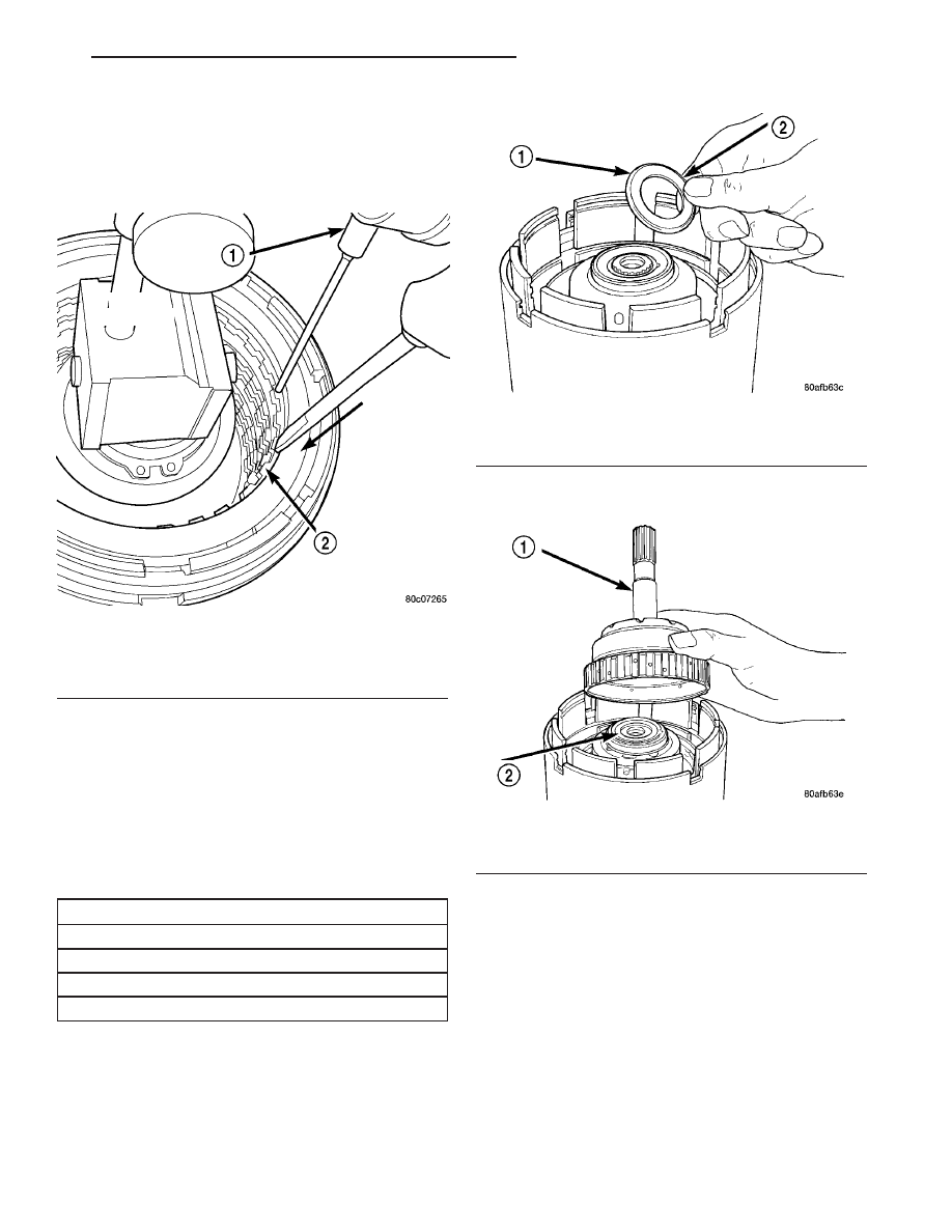
(33) Using moderate pressure, press down and

hold (near indicator) reverse clutch disc with screw-
driver or suitable tool and zero dial indicator (Fig.
310). When releasing pressure, indicator should
advance 0.005-0.010. as clutch pack relaxes.

(34) Apply 30 psi (206 kPa) air pressure to the

reverse clutch hose on Tool 8391. Measure and record
reverse clutch pack measurement in four (4) places,
90° apart.

(35) Take average of four measurements and com-

pare with reverse clutch pack clearance specification.
The reverse clutch pack clearance is 0.89-1.37
mm (0.035-0.054 in.). 
Select the proper reverse
clutch snap ring to achieve specifications:

REVERSE CLUTCH SNAP RING THICKNESS

4377195

1.53-1.58 mm (0.060-0.062 in.)

4412871

1.77-1.83 mm (0.070-0.072 in.)

4412872

2.02-2.07 mm (0.080-0.082 in.)

4412873

2.27-2.32 mm (0.090-0.091 in.)

(36) To complete the assembly, reverse clutch and

overdrive clutch must be removed.

(37) Install the #2 needle bearing (Fig. 311).

(38) Install the underdrive shaft assembly (Fig.

312).

(39) Install the #3 thrust washer to the underdrive

shaft assembly. Be sure five tabs are seated properly
(Fig. 313).

Fig. 310 Press Down on Reverse Clutch and Zero

Indicator

1 - DIAL INDICATOR
2 - REVERSE CLUTCH

Fig. 311 Install No. 2 Needle Bearing

1 - #2 NEEDLE BEARING (NOTE 3 SMALL TABS)
2 - TABS UP

Fig. 312 Install Underdrive Shaft Assembly

1 - UNDERDRIVE SHAFT ASSEMBLY
2 - #2 NEEDLE BEARING

CS

41AE/TE AUTOMATIC TRANSAXLE

21 - 131

INPUT CLUTCH ASSEMBLY (Continued)

(40) Install the #3 thrust plate to the bottom of the

overdrive shaft assembly. Retain with petrolatum or
transmission assembly gel (Fig. 314).

(41) Install the overdrive shaft assembly (Fig. 315)

(Fig. 316).

(42) Reinstall overdrive and reverse clutch as

shown. Rechecking these clutch clearances is
not necessary.

Fig. 313 Install No. 3 Thrust Washer

1 - #3 THRUST WASHER (NOTE 5 TABS)
2 - UNDERDRIVE SHAFT ASSEMBLY

Fig. 314 Install No. 3 Thrust Plate

1 - OVERDRIVE SHAFT ASSEMBLY
2 - DABS OF PETROLATUM (FOR RETENTION)
3 - #3 THRUST PLATE (NOTE 3 TABS)

Fig. 315 Install Overdrive Shaft Assembly

1 - OVERDRIVE SHAFT ASSEMBLY
2 - #3 THRUST PLATE
3 - #3 THRUST WASHER

21 - 132

41AE/TE AUTOMATIC TRANSAXLE

CS

INPUT CLUTCH ASSEMBLY (Continued)

Fig. 316 Overdrive/Underdrive Shafts

1 - OVERDRIVE SHAFT
2 - #3 THRUST PLATE (3 TABS)
3 - #3 THRUST WASHER (5 TABS)

4 - UNDERDRIVE SHAFT
5 - #2 NEEDLE BEARING (3 TABS)
6 - INPUT CLUTCH ASSEMBLY

CS

41AE/TE AUTOMATIC TRANSAXLE

21 - 133

INPUT CLUTCH ASSEMBLY (Continued)

OIL PUMP

DESCRIPTION

The oil pump is located in the pump housing inside

the bell housing of the transaxle case (Fig. 317). The
oil pump consists of an inner and outer gear, a hous-
ing, and a cover that also serves as the reaction shaft
support.

OPERATION

As the torque converter rotates, the converter hub

rotates the inner and outer gears. As the gears
rotate,

the

clearance

between

the

gear

teeth

increases in the crescent area, and creates a suction
at the inlet side of the pump. This suction draws
fluid through the pump inlet from the oil pan. As the
clearance between the gear teeth in the crescent area
decreases, it forces pressurized fluid into the pump
outlet and to the valve body.

DISASSEMBLY

When disassembling the transaxle it is necessary

to inspect the oil pump for wear and damage.

(1) Remove the reaction shaft support-to-pump

body bolts (Fig. 318).

(2) Remove reaction shaft support from pump

housing (Fig. 319).

(3) Remove the pump gears (Fig. 320) and check

for wear and damage on pump housing and gears.

Fig. 317 Oil Pump Assembly

1 - PUMP BODY
2 - OUTER GEAR
3 - INNER GEAR
4 - REACTION SHAFT SUPPORT
5 - SEAL RINGS (4)
6 - REACTION SHAFT
7 - CRESCENT

Fig. 318 Reaction Support-to-Pump Body Bolts

1 - BOLT (6)
2 - PUMP BODY
3 - REACTION SHAFT SUPPORT

Fig. 319 Reaction Shaft Support

1 - PUMP BODY
2 - PUMP GEARS
3 - REACTION SHAFT SUPPORT

21 - 134

41AE/TE AUTOMATIC TRANSAXLE

CS


Content   ..  782  783  784  785   ..