Chrysler Pacifica. Manual - part 777


  Index      Chrysler     Chrysler Pacifica - service repair manual 2005 year


Search            


Content   ..  775  776  777  778   ..


Chrysler Pacifica. Manual - part 777


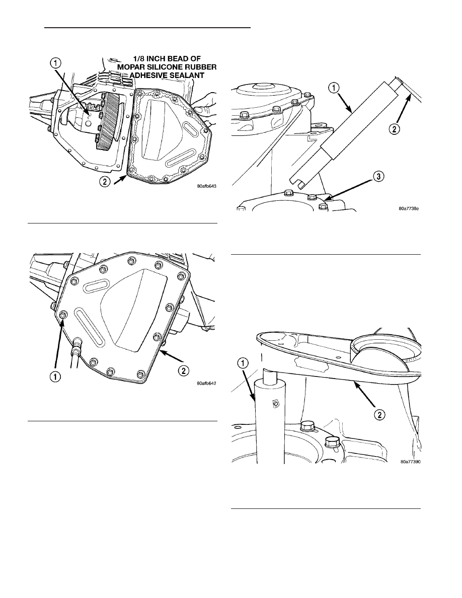
(18) Install and torque cover-to-case bolts to 19

N·m (165 in. lbs.) (Fig. 246).

ADJUSTMENTS

ADJUSTMENT - DIFFERENTIAL BEARING
PRELOAD

NOTE: Perform all differential bearing preload mea-
surements

with

the

transfer

shaft

and

gear

removed.

DIFFERENTIAL BEARING PRELOAD ADJUSTMENT
USING EXISTING SHIM

(1) Position the transaxle assembly vertically on

the support stand, differential bearing retainer side
up.

(2) Install Tool L-4436A into the differential and

onto the pinion mate shaft (Fig. 247).

(3) Rotate the differential at least one full revolu-

tion to ensure the tapered roller bearings are fully
seated.

(4) Using Tool L-4436A and an inch-pound torque

wrench, check the turning torque of the differential
(Fig.

248).

The

turning

torque

should

be

between 5 and 18 inch-pounds.

(5) If the turning torque is within specifications,

remove tools. Setup is complete.

(6) If turning torque is not within specifications

proceed with the following steps.

Fig. 245 Install Differential Cover

1 - DIFFERENTIAL ASSEMBLY
2 - DIFFERENTIAL COVER

Fig. 246 Differential Cover Bolts

1 - DIFFERENTIAL COVER BOLTS
2 - DIFFERENTIAL COVER

Fig. 247 Tool L-4436 and Torque Wrench

1 - SPECIAL TOOL L-4436–A
2 - TORQUE WRENCH
3 - DIFFERENTIAL BEARING RETAINER

Fig. 248 Checking Differential Bearings Turning

Torque

1 - SPECIAL TOOL L-4436–A
2 - TORQUE WRENCH

CS

41AE/TE AUTOMATIC TRANSAXLE

21 - 103

FINAL DRIVE (Continued)

(a) Remove differential bearing retainer from

the transaxle case.

(b) Remove the bearing cup from the differential

bearing retainer using Tool 6062A.

(c) Remove the existing shim from under the

cup.

(d) Measure the existing shim.
(e) If the turning torque was too high when mea-

sured, install a 0.05 mm (0.002 inch) thinner shim.
If the turning torque is was too low, install a 0.05
mm (0.002 inch) thicker shim. Repeat until 5-18
inch-pounds turning torque is obtained. Oil Baffle
is not required to be installed when making shim
selection.

(f) Install the proper shim under the bearing

cup. Make sure the oil baffle is installed properly
in the bearing retainer, below the bearing shim
and cup.

(g) Install the differential bearing retainer using

Tool 5052 and C-4171. Seal the retainer to the
housing with MOPAR

t Silicone Rubber Adhesive

Sealant and torque bolts to 28 N·m (250 in. lbs.).
(7) Using Tool L-4436A and an inch-pound torque

wrench, recheck the turning torque of the differential
(Fig. 248). The turning torque should be within
5-18 inch-pounds.

Shim thickness need be determined only if any of

the following parts are replaced:

• Transaxle case

• Differential carrier

• Differential bearing retainer

• Extension housing

• Differential bearing cups and cones

DIFFERENTIAL BEARING SHIM CHART

PART NUMBER

SHIM

THICKNESS

MM

INCH

4659257

.980

0.0386

4659258

1.02

0.0402

4659259

1.06

0.0418

4659260

1.10

0.0434

4659261

1.14

0.0449

4659262

1.18

0.0465

4659263

1.22

0.0481

4659264

1.26

0.0497

4659265

1.30

0.0512

4659266

1.34

0.0528

4659267

1.38

0.0544

4659268

1.42

0.0560

4659269

1.46

0.0575

4659270

1.50

0.0591

4659271

1.54

0.0607

4659272

1.58

0.0623

4659273

1.62

0.0638

4659274

1.66

0.0654

4659275

1.70

0.0670

4659283

2.02

0.0796

4659284

2.06

0.0812

21 - 104

41AE/TE AUTOMATIC TRANSAXLE

CS

FINAL DRIVE (Continued)

PRELOAD ADJUSTMENT W/O SHIM

(1) Remove the bearing cup from the differential

bearing retainer using Miller special Tool 6062A.

(2) Remove existing shim from under bearing cup.
(3) Reinstall the bearing cup into the retainer

using Miller Special Tool 6061, and C-4171.

NOTE: Oil baffle is not required when making the
shim calculation.

(4) Install the bearing retainer into the case.

Torque bolts to 28 N·m (250 in. lbs.).

(5) Position the transaxle assembly vertically on

the support stand and install Miller Special Tool
L-4436-A into the bearing retainer.

(6) Rotate the differential at least one full revolu-

tion to ensure the tapered roller bearings are fully
seated.

(7) Attach a dial indicator to the case and zero the

dial. Place the tip on the end of Special Tool
L-4436-A.

(8) Place a large screwdriver to each side of the

ring gear and lift. Check the dial indicator for the
amount of end play.

CAUTION: Do not damage the transaxle case and/or
differential retainer sealing surface.

(9) Using the end play measurement that was

determined, add 0.18mm (0.007 inch). This should
give you between 5-18 inch pounds of bearing pre-
load. Refer to the Differential Bearing Shim Chart to
determine which shim to use.

(10) Remove

the

differential

bearing

retainer.

Remove the bearing cup.

(11) Install the oil baffle. Install the proper shim

combination under the bearing cup.

(12) Install the differential bearing retainer. Seal

the retainer to the housing with Mopar

t Silicone

Rubber Adhesive Sealant. Torque bolts to 28 N·m
(250 in. lbs.).

(13) Using Miller Special Tool L-4436-A and an

inch-pound torque wrench, check the turning torque
of the differential (Fig. 248). The turning torque
should be between 5-18 inch-pounds.

NOTE: If turning torque is too high install a 0.05mm
(0.002 inch) thicker shim. If the turning torque is too
low, install a 0.05mm (0.002 inch) thinner shim.
Repeat until 5-18 inch-pounds of turning torque is
obtained.

FLUID

STANDARD PROCEDURE

FLUID LEVEL AND CONDITION CHECK

NOTE: Only transmission fluid of the type labeled
Mopar

ATF+4

(Automatic

Transmission

Fluid)

should be used in this transaxle.

FLUID LEVEL CHECK

The transmission sump has a fluid level indicator

(dipstick) to check oil similar to most automatic
transmissions. It is located on the left side of the
engine. Be sure to wipe all dirt from dipstick handle
before removing.

The torque converter fills in both the P Park and N

Neutral positions. Place the selector lever in P Park
to be sure that the fluid level check is accurate. The
engine should be running at idle speed for at
least one minute, with the vehicle on level
ground. 
At normal operating temperature 82° C
(180° F), the fluid level is correct if it is in the HOT
region on the oil level indicator (Fig. 249). The fluid
level should be within the COLD region of the dip-
stick at 27° C (80° F) fluid temperature.

FLUID LEVEL CHECK USING DRB

NOTE: Engine and Transaxle should be at normal
operating temperature before performing this proce-
dure.

(1) Start engine and apply parking brake.
(2) Hook up DRB scan tool and select transmis-

sion.

Fig. 249 Fluid Level Indicator

1 - FLUID LEVEL INDICATOR

CS

41AE/TE AUTOMATIC TRANSAXLE

21 - 105

FINAL DRIVE (Continued)

(3) Select sensors.
(4) Read the transmission temperature value.
(5) Compare the fluid temperature value with the

fluid temperature chart (Fig. 250).

(6) Adjust transmission fluid level shown on the

indicator according to the chart.

(7) Check transmission for leaks.
Low fluid level can cause a variety of conditions

because it allows the pump to take in air along with
the fluid. As in any hydraulic system, air bubbles
make the fluid spongy, therefore, pressures will be
low and build up slowly.

Improper filling can also raise the fluid level too

high. When the transaxle has too much fluid, the
gears churn up foam and cause the same conditions
which occur with a low fluid level.

In either case, air bubbles can cause overheating

and/or fluid oxidation, and varnishing. This can
interfere with normal valve, clutch, and accumulator
operation. Foaming can also result in fluid escaping
from the transaxle vent where it may be mistaken
for a leak.

FLUID CONDITION

Along with fluid level, it is important to check the

condition of the fluid. When the fluid smells burned,
and is contaminated with metal or friction material
particles, a complete transaxle recondition is proba-
bly required. Be sure to examine the fluid on the dip-
stick closely. If there is any doubt about its condition,
drain out a sample for a double check.

Mopar

t ATF+4 (Automatic Transmission Fluid)

when new is red in color. The ATF is dyed red so it
can be identified from other fluids used in the vehicle
such as engine oil or antifreeze. The red color is not
permanent and is not an indicator of fluid condition.
As the vehicle is driven, the ATF will begin to look
darker in color and may eventually become brown.
This is normal. ATF+4 also has a unique odor that
may change with age. Consequently, odor and color
cannot be used to indicate the fluid condition
or the need for a fluid change.

After the fluid has been checked, seat the dipstick

fully to seal out water and dirt.

Fig. 250 Transmission Fluid Temperature Chart

1 - MAX. LEVEL

2 - MIN. LEVEL

21 - 106

41AE/TE AUTOMATIC TRANSAXLE

CS

FLUID (Continued)


Content   ..  775  776  777  778   ..