Chrysler Pacifica. Manual - part 724
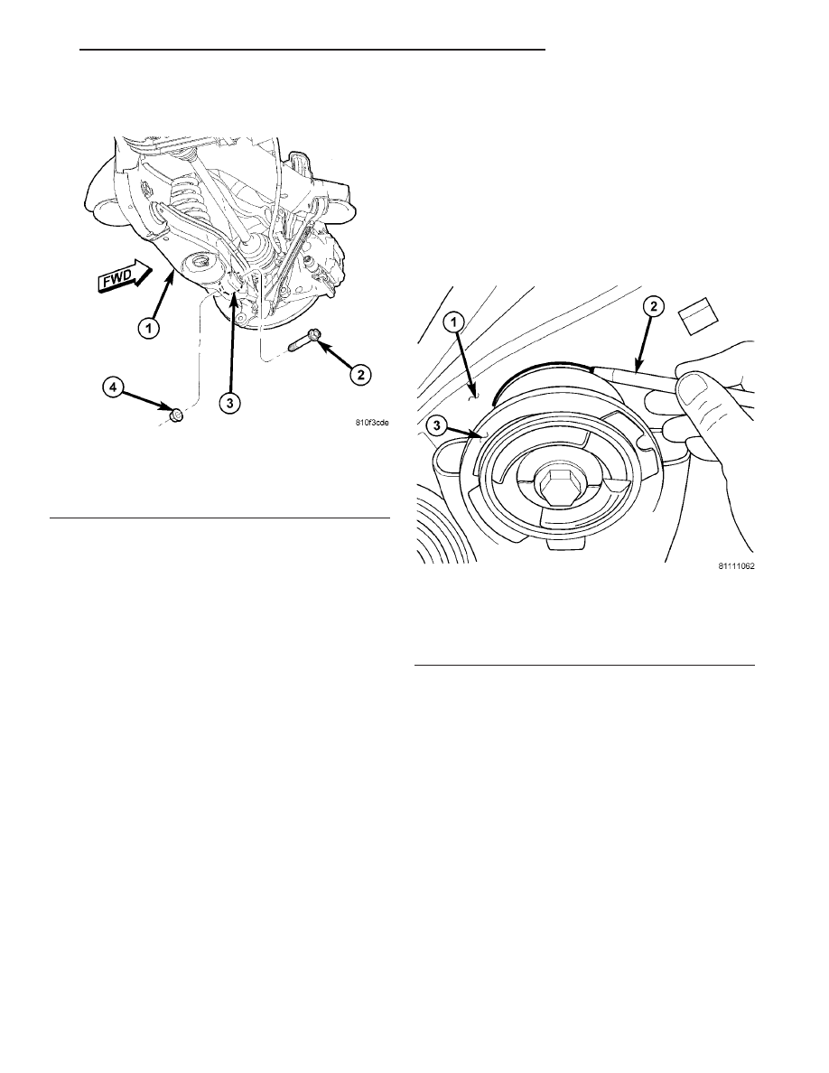
(13) Install lower shock mounting bolt (Fig. 78).
Do not tighten at this time.
(14) Raise right side of crossmember into mounted
position. Install right side crossmember mounting
bolts (Fig. 76). Do not fully tighten bolts at this
time.
(15) Remove both front and rear crossmember
mounting bolts on left side of vehicle (Fig. 76).
CAUTION: To avoid damaging other components of
vehicle, do not lower crossmember any further than
necessary to install coil spring.
(16) Slowly lower jack allowing left side of cross-
member to drop. Do not lower jack at a fast rate.
Lower jack just enough to allow spring installation.
Do not lower jack any further than necessary.
(17) Install coil spring and isolator (Fig. 77), top
end first.
NOTE: Verify that spring lower end coil is correctly
placed against abutment built into spring link.
(18) Carefully raise jack, guiding coil spring and
lower end of shock absorber into mounted positions.
Once shock absorber lower mounting hole lines up
with hole in spring link, stop jacking.
(19) Install lower shock mounting bolt (Fig. 78).
Do not tighten at this time.
(20) Raise left side of crossmember into mounted
position and install previously removed mounting
bolts (Fig. 76). Do not fully tighten bolts at this
time.
(21) Shift crossmember as necessary to line up
mounts with location marks drawn in before removal
(Fig. 79).
NOTE: If proper location marks are unavailable or
as a check, the crossmember can be positioned uti-
lizing the PLP points. Shift the crossmember as
necessary
to
achieve
the
measured
distances
shown in the figure (Fig. 80).
(22) Once mounts are lined up with location
marks, tighten all four crossmember mounting bolts
to 163 N·m (120 ft. lbs.) torque.
(23) Tighten shock absorber lower mounting bolts
to 102 N·m (75 ft. lbs.) torque.
(24) Remove jack from under crossmember.
(25) If equipped with AWD, install rear driveline
module and both rear half shafts. (Refer to 3 - DIF-
FERENTIAL
&
DRIVELINE/REAR
DRIVELINE
MODULE - INSTALLATION)
Fig. 78 Shock Absorber Mounting - Lower
1 - SPRING LINK
2 - BOLT
3 - SHOCK ABSORBER
4 - NUT
Fig. 79 Marking Location Of Crossmember Mount
To Body
1 - BODY
2 - MARKER (OR CRAYON)
3 - CROSSMEMBER BUSHING FLANGE
CS
FRAME & BUMPERS
13 - 35
REAR CROSSMEMBER (Continued)