Chrysler Pacifica. Manual - part 720
SPECIAL TOOLS
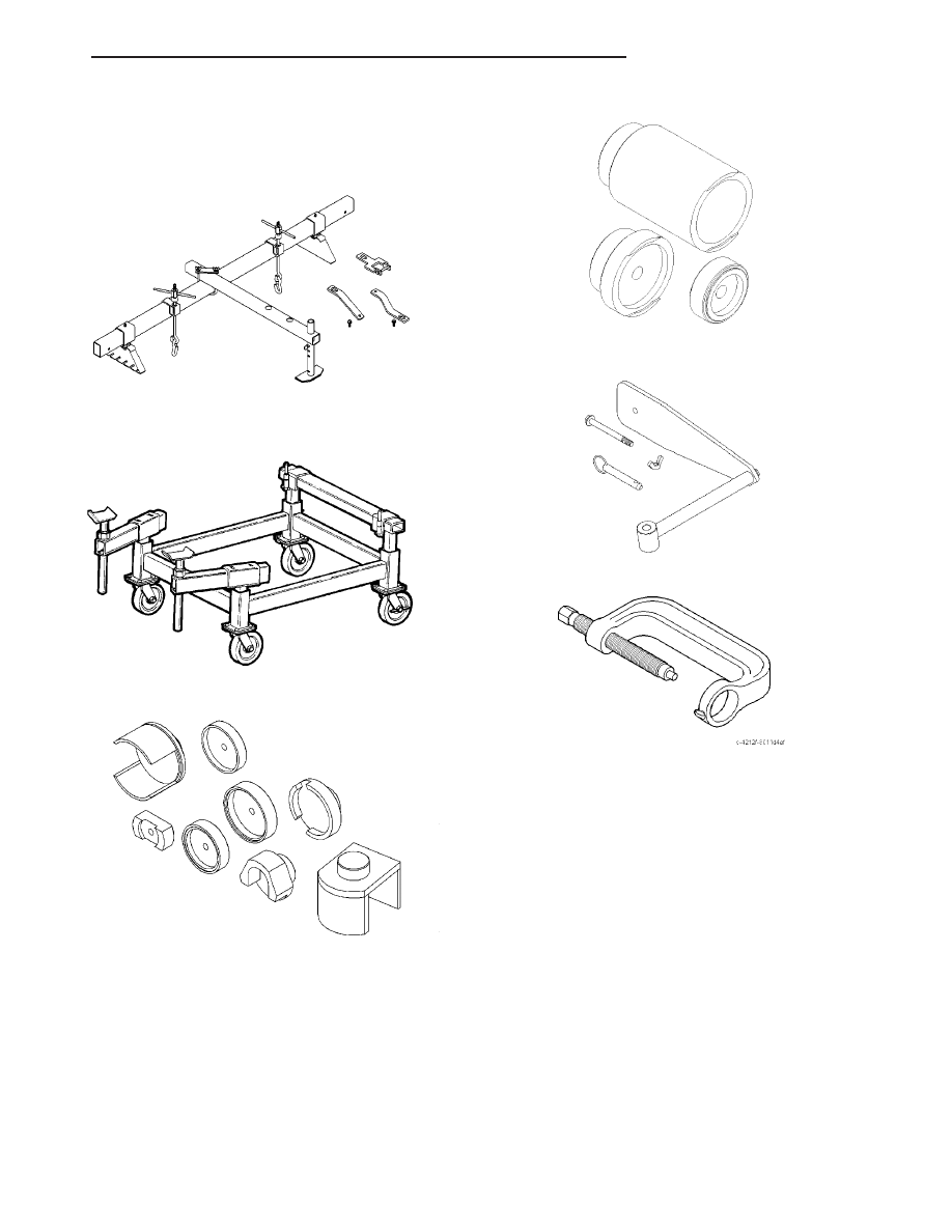
FRAME
Driveline Support Fixture 8534B
Driveline Support Table 8874
Remover/Installer, Bushing 9031
Remover/Installer, Bushing 9032
Gage, Curb Height 9094
Press, Ball Joint C-4212F
CS
FRAME & BUMPERS
13 - 19
FRAME (Continued)