Chrysler Pacifica. Manual - part 706


  Index      Chrysler     Chrysler Pacifica - service repair manual 2005 year


Search            


Content   ..  704  705  706  707   ..


Chrysler Pacifica. Manual - part 706


INSTALLATION

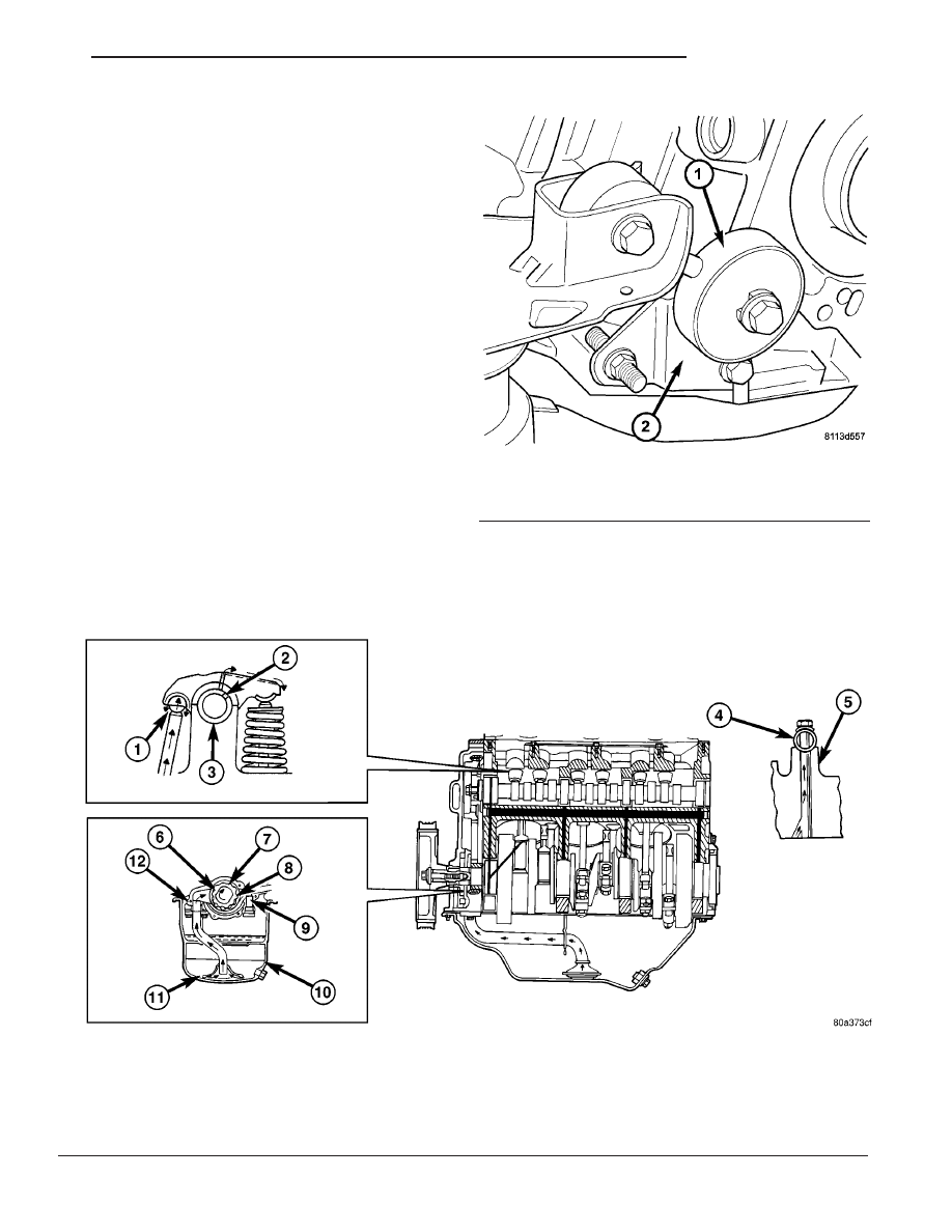
(1) Install the torque strut (Fig. 122). Tighten the

fasteners to 54 N·m (40 ft.lbs.).

(2) Remove the floor jack
(3) Lower the vehicle.
(4) Reconnect the negative battery cable.

LUBRICATION

DESCRIPTION

The lubrication system is a full flow filtration pres-

sure feed type. The oil pump is mounted in the tim-
ing chain cover and is driven by the crankshaft

OPERATION

Oil from the oil pan is pumped by a internal gear

type oil pump directly coupled to the crankshaft. The
pressure is regulated by a relief valve located in the
timing chain cover. The oil is pumped through an oil
filter and feeds a main oil gallery. This oil gallery
feeds oil under pressure to the main and rod bear-
ings, camshaft bearings. Passages in the cylinder
block feed oil to the hydraulic lifters and rocker shaft
brackets which feeds the rocker arm pivots (Fig.
123).

Fig. 122 Powertrain Torque Strut

1 - STRUT
2 - BRACKET

Fig. 123 ENGINE LUBRICATION

1 - OIL SUPPLY FOR BALL SOCKET THROUGH PUSH ROD

7 - OUTER ROTOR

2 - OIL SUPPLY PASSAGE FROM SHAFT TO ROCKER ARM

8 - INNER ROTOR

3 - ROCKER SHAFT

9 - RELIEF VALVE

4 - OIL FLOWS TO ONLY ONE PEDASTAL ON EACH HEAD; THIRD
FROM REAR ON RIGHT HEAD, THIRD FROM FRONT ON LEFT HEAD

10 - OIL PAN

5 - ROCKER SHAFT TOWER

11 - OIL SCREEN

6 - CRANKSHAFT

12 - OIL PUMP CASE

CS

ENGINE 3.8L

9 - 179

TORQUE STRUT (Continued)

DIAGNOSIS AND TESTING - ENGINE OIL
PRESSURE

(1) Disconnect and remove oil pressure switch

(Refer to 9 - ENGINE/LUBRICATION/OIL PRES-
SURE SENSOR/SWITCH - REMOVAL).

(2) Install Special Tools C-3292 Gauge with 8406

Adaptor. For Special Tool identification, (Refer to 9 -
ENGINE - SPECIAL TOOLS).

(3) Start engine and record oil pressure. Refer to

Oil Pressure in Engine Specifications for the correct
pressure (Refer to 9 - ENGINE - SPECIFICATIONS).

OIL

STANDARD PROCEDURE

STANDARD PROCEDURE - ENGINE OIL AND
FILTER CHANGE

Change engine oil at mileage and time intervals

described in the Maintenance Schedule. (Refer to
LUBRICATION

&

MAINTENANCE/MAINTE-

NANCE SCHEDULES - DESCRIPTION)

WARNING: NEW OR USED ENGINE OIL CAN BE
IRRITATING TO THE SKIN. AVOID PROLONGED OR
REPEATED SKIN CONTACT WITH ENGINE OIL.
CONTAMINANTS IN USED ENGINE OIL, CAUSED BY
INTERNAL COMBUSTION, CAN BE HAZARDOUS TO
YOUR HEALTH. THOROUGHLY WASH EXPOSED
SKIN WITH SOAP AND WATER. DO NOT WASH
SKIN WITH GASOLINE, DIESEL FUEL, THINNER, OR
SOLVENTS, HEALTH PROBLEMS CAN RESULT. DO
NOT POLLUTE, DISPOSE OF USED ENGINE OIL
PROPERLY. CONTACT YOUR DEALER OR GOVERN-
MENT AGENCY FOR LOCATION OF COLLECTION
CENTER IN YOUR AREA.

Run engine until achieving normal operating tem-

perature.

(1) Position the vehicle on a level surface and turn

engine off.

(2) Open hood, remove oil fill cap (Fig. 125).
(3) Hoist and support vehicle on safety stands.

Refer to Hoisting and Jacking Recommendations.
(Refer to LUBRICATION & MAINTENANCE/HOIST-
ING - STANDARD PROCEDURE)

(4) Place a suitable drain pan under crankcase

drain (Fig. 124).

(5) Remove drain plug from crankcase (Fig. 124)

and allow oil to drain into pan. Inspect drain plug
threads for stretching or other damage. Replace
drain plug and gasket if damaged.

(6) Remove oil filter. (Refer to 9 - ENGINE/LUBRI-

CATION/OIL FILTER - REMOVAL)

(7) Install and tighten drain plug in crankcase.
(8) Install new oil filter. (Refer to 9 - ENGINE/LU-

BRICATION/OIL FILTER - INSTALLATION)

(9) Lower vehicle and fill crankcase with specified

type and amount of engine oil. (Refer to LUBRICA-
TION

&

MAINTENANCE/FLUID

TYPES

-

DESCRIPTION)

(10) Install oil fill cap.
(11) Start engine and inspect for leaks.
(12) Stop engine and inspect oil level.

NOTE: Care should be exercised when disposing
used engine oil after it has been drained from a
vehicle engine. Refer to the WARNING listed above.

Fig. 124 DRAIN PLUG AND OIL FILTER

1 - DRAIN PLUG
2 - OIL FILTER

9 - 180

ENGINE 3.8L

CS

LUBRICATION (Continued)

STANDARD PROCEDURE - ENGINE OIL LEVEL
CHECK

The best time to check engine oil level is after it

has sat overnight, or if the engine has been running,
allow the engine to be shut off for at least 5 minutes
before checking oil level.

Checking the oil while the vehicle is on level

ground will improve the accuracy of the oil level
reading (Fig. 125). Add engine oil only when the level
is at or below the ADD mark on the indicator.

OIL COOLER & LINES

DESCRIPTION

An engine oil cooler is used on 3.8L engines (Heavy

Duty Cooling Only) (Fig. 126). The cooler is a cool-
ant-to-oil type and mounted between the oil filter
and engine block.

Fig. 125 ENGINE OIL FILL AND INDICATOR

1 - ENGINE COOLANT RESERVOIR

4 - ENGINE OIL FILL

2 - MASTER CYLINDER

5 - OIL LEVEL INDICATOR

3 - TRANSMISSION OIL LEVEL INDICATOR

6 - POWER STEERING RESERVOIR

Fig. 126 ENGINE OIL COOLER

1 - OIL FILTER ADAPTER
2 - CONNECTOR
3 - ENGINE OIL COOLER
4 - OIL COOLER ATTACHMENT FITTING
5 - OIL FILTER

CS

ENGINE 3.8L

9 - 181

OIL (Continued)

OPERATION

Engine oil travels from the oil filter and into the

oil cooler. Engine oil then exits the cooler into the
main gallery. Engine coolant flows into the cooler
from the heater return tube and exits into the water
pump inlet.

REMOVAL

(1) Drain cooling system (Refer to 7 - COOLING -

STANDARD PROCEDURE - COOLING SYSTEM
DRAINING).

(2) Disconnect oil cooler inlet and outlet hoses

(Fig. 127).

(3) Remove oil filter.
(4) Remove oil cooler attachment fitting (Fig. 128).
(5) Remove oil cooler.

INSTALLATION

(1) Lubricate seal and position oil cooler to connec-

tor fitting on oil filter adapter (Fig. 129).

NOTE: Position the flat side of oil cooler parallel to
oil pan rail.

(2) Install oil cooler attachment fitting and tighten

to 27 N·m (20 ft. lbs.) (Fig. 129).

(3) Install oil filter.

Fig. 127 ENGINE OIL COOLER LINES

1 - OIL COOLER INLET TUBE
2 - INLET HOSE
3 - OIL COOLER OUTLET TUBE
4 - OUTLET HOSE
5 - WATER PUMP INLET TUBE

Fig. 128 ENGINE OIL COOLER

1 - OIL FILTER ADAPTER
2 - CONNECTOR
3 - ENGINE OIL COOLER
4 - OIL COOLER ATTACHMENT FITTING
5 - OIL FILTER

Fig. 129 ENGINE OIL COOLER

1 - OIL FILTER ADAPTER
2 - CONNECTOR
3 - ENGINE OIL COOLER
4 - OIL COOLER ATTACHMENT FITTING
5 - OIL FILTER

9 - 182

ENGINE 3.8L

CS

OIL COOLER & LINES (Continued)


Content   ..  704  705  706  707   ..