Chrysler Pacifica. Manual - part 697


  Index      Chrysler     Chrysler Pacifica - service repair manual 2005 year


Search            


Content   ..  695  696  697  698   ..


Chrysler Pacifica. Manual - part 697


(1) When refacing valve seats, it is important that

the correct size valve guide pilot be used for reseat-
ing stones. A true and complete surface must be
obtained.

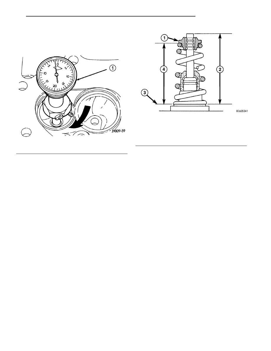
(2) Measure the concentricity of valve seat using

dial indicator (Fig. 41). Total runout should not
exceed 0.051 mm (0.002 in.) total indicator reading.

(3) Inspect the valve seat using Prussian blue to

determine where the valve contacts the seat. To do
this, coat valve seat LIGHTLYwith Prussian blue
then set valve in place. Rotate the valve with light
pressure. If the blue is transferred to the center of
valve face, contact is satisfactory. If the blue is trans-
ferred to top edge of valve face, lower valve seat with
a 15 degree stone. If the blue is transferred to the
bottom edge of valve face raise valve seat with a 65
degrees stone.

NOTE: Valve seats which are worn or burned can
be reworked, provided that correct angle and seat
width are maintained. Otherwise cylinder head must
be replaced.

(4) When seat is properly positioned the width of

intake and exhaust seats should be 1.50–2.00 mm
(0.059–0.078 in.) (Fig. 38).

(5) After grinding the valve seats or faces, install

the valve in cylinder head and check valve installed
height by measuring from valve tip to spring seat
(Fig. 42). Remove valve from cylinder head and grind
valve tip until within specifications. Check valve tip
for scoring. The tip chamfer should be reground (if
necessary) to prevent seal damage when the valve is
installed.

(6) Check the valve spring installed height after

refacing the valve and seat (Fig. 42).

If valves and/or seats are reground, measure

the installed height of springs (Fig. 42), make
sure measurements are taken from top of
spring seat to the bottom surface of spring
retainer. If height is greater than specifica-
tions, install a 0.794 mm (0.0312 in.) spacer in
head counterbore to bring spring height back
within specifications.

Fig. 41 Measurement of Valve Seat Runout

1 - DIAL INDICATOR

Fig. 42 VALVE INSTALLED HEIGHT

1 - SPRING RETAINER
2 - VALVE INSTALLED HEIGHT* - 48.1–49.7 mm (1.89–1.95 in.)
3 - CYINDER HEAD SURFACE
4 - SPRING INSTALLED HEIGHT* - 41.1–42.7 mm (1.61–1.68 in.)

*(MEASURED FROM TOP OF SPRING SEAT)

CS

ENGINE 3.8L

9 - 143

INTAKE/EXHAUST VALVES & SEATS (Continued)

REMOVAL

(1) With cylinder head removed, compress valve

springs

using

Valve

Spring

Compressor

Tool

C-3422-D with adapter 8464 (Fig. 43).

(2) Remove valve retaining locks (Fig. 44).
(3) Slowly

release

valve

spring

compressor.

Remove valve spring retainer, valve spring, and valve
stem seal.

(4) Before removing valves, remove any burrs

from valve stem lock grooves to prevent dam-
age to the valve guides. 
Identify valves to insure
installation in original location.

CLEANING

(1) Clean

all

valves

thoroughly

and

discard

burned, warped and cracked valves.

INSPECTION

VALVES

(1) Clean and inspect valves thoroughly. Replace

burned, warped and cracked valves.

Fig. 43 VALVE SPRING - REMOVE/INSTALL

1 - SPECIAL TOOL C-3422-D SPRING COMPRESSOR
2 - SPECIAL TOOL 8464 ADAPTER

Fig. 44 VALVE COMPONENTS

1 - VALVE LOCKS

5 - SPRING SEATS

2 - RETAINERS

6 - CYLINDER HEAD

3 - VALVE SPRINGS

7 - VALVE - EXHAUST

4 - VALVE STEM SEALS

8 - VALVE - INTAKE

9 - 144

ENGINE 3.8L

CS

INTAKE/EXHAUST VALVES & SEATS (Continued)

(2) Measure valve stems for wear (Fig. 45). For

valve specifications, (Refer to 9 - ENGINE - SPECI-
FICATIONS).

NOTE: Valve stems are chrome plated and should
not be polished (Fig. 45).

VALVE GUIDES

(1) Remove carbon and varnish deposits from

inside of valve guides with a reliable guide cleaner.

(2) Measure valve stem-to-guide clearance as fol-

lows:

(3) Install valve into cylinder head so it is 15 mm

(0.590 inch.) off the valve seat. A small piece of hose
may be used to hold valve in place.

(4) Attach dial indicator Tool C-3339 to cylinder

head and set it at right angle of valve stem being
measured (Fig. 46).

(5) Move valve to and from the indicator. For cler-

ance specifications, (Refer to 9 - ENGINE - SPECIFI-
CATIONS).

NOTE: Replace cylinder head if stem-to-guide clear-
ance exceeds specifications, or if guide is loose in
cylinder head.

INSTALLATION

(1) Coat valve stems with clean engine oil and

insert them in cylinder head (Fig. 47).

(2) Install valve spring seat on head (Fig. 47).
(3) Install new seals on all valve stems and over

valve guides Install valve springs and valve retainers
(Fig. 48)

(4) Install

the

valve

springs.

(Refer

to

9

-

ENGINE/CYLINDER

HEAD/VALVE

SPRINGS

-

INSTALLATION)

Fig. 45 Intake and Exhaust Valves

1 - MARGIN
2 - FACE
3 - STEM
4 - VALVE SPRING RETAINER LOCK GROOVES

Fig. 46 Measuring Valve Guide Wear

CS

ENGINE 3.8L

9 - 145

INTAKE/EXHAUST VALVES & SEATS (Continued)

Fig. 47 VALVE COMPONENTS

1 - VALVE LOCKS

5 - SPRING SEATS

2 - RETAINERS

6 - CYLINDER HEAD

3 - VALVE SPRINGS

7 - VALVE - EXHAUST

4 - VALVE STEM SEALS

8 - VALVE - INTAKE

Fig. 48 VALVE STEM SEAL

9 - 146

ENGINE 3.8L

CS

INTAKE/EXHAUST VALVES & SEATS (Continued)


Content   ..  695  696  697  698   ..