Chrysler Pacifica. Manual - part 666


  Index      Chrysler     Chrysler Pacifica - service repair manual 2005 year


Search            


Content   ..  664  665  666  667   ..


Chrysler Pacifica. Manual - part 666


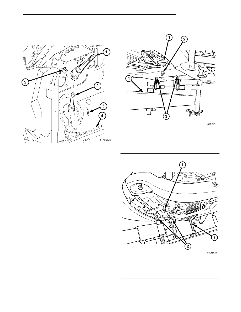
(59) Remove the lower steering column coupling

pin with special tool 6831–A, and separate union.
(Fig. 12).

(60) Remove both lower engine mount nuts (Fig.

13).

(61) Paint mark the front cradle to body location

and position the engine cradle support under the
vehicle (Fig. 13).

(62) Lower the vehicle until just above the cradle

support fixture (Fig. 13).

(63) Align the cradle support dowels with the cra-

dle access holes (Fig. 13).

(64) Adjust engine support fixture to fit flush with

the oil pan and adjust cradle support fixture arms to
fit flush with cradle (Fig. 14).

(65) Carefully lower the vehicle onto the cradle

support fixture.

(66) Remove the upper engine mount (Refer to 9 -

ENGINE/ENGINE MOUNTING/FRONT MOUNT -
REMOVAL).

CAUTION: While slowly separating the body from
the cradle assembly, constant checks must be
made to assure proper positioning and that no
damage to other components or wiring harnesses
occur during separation.

(67) Carefully remove the front and rear cradle

mounting bolts and raise the vehicle to separate the

Fig. 12 STEERING COLUMN COUPLING

1 - LOWER STEERING COLUMN COUPLING ASSEMBLY
2 - INTERMEDIATE SHAFT TO STEERING GEAR
3 - PIN
4 - STEERING GEAR
5 - EXTENSION TO SHAFT BOLT

Fig. 13 CRADLE SUPPORT FIXTURE - REAR

1 - RIGHT LOWER ENGINE MOUNT
2 - RIGHT LOWER ENGINE MOUNT NUT
3 - ALIGNMENT DOWEL ACCESS HOLES
4 - CRADLE SUPPORT FIXTURE

Fig. 14 CRADLE SUPPORT FIXTURE - FRONT

1 - LEFT LOWER ENGINE MOUNT NUT
2 - CRADLE SUPPORT FIXTURE ARMS
3 - CRADLE SUPPORT FIXTURE ENGINE STABILIZER

CS

ENGINE 3.5L

9 - 19

ENGINE 3.5L (Continued)

engine, transmission and cradle assembly from the
vehicle.

(68) Connect engine lifting brackets to engine (Fig.

15)

(69) Separate the Power Transfer Unit (PTU), (if

equipped).

(70) Separate the engine and transmission from

the engine cradle using the lifting brackets. (Fig. 15).

(71) Separate the transmission from the engine.

INSTALLATION - ENGINE ASSEMBLY

(1) Install transmission and power transfer unit

(PTU) (if equipped), onto engine assembly.

(2) Mount engine assembly onto cradle assembly.
(3) Carefully position the engine cradle assembly

under the vehicle.

CAUTION: While slowly lowering the body to the
cradle assembly, constantly check to assure proper
positioning and no damage occurs to other compo-
nents or harnesses until union is made.

(4) Lower the vehicle until the union is made

between the cradle assembly and body, taking care to
align the cradle to body marks.

(5) Install the cradle supporting bolts and tighten

to 163 N·m (120 lbs. ft.).

(6) Install upper engine mount, tighten bolt to tim-

ing cover to 54 N·m (40 lbs. ft.). Tighten bolt to right
rail 68 N·m (50 lbs.ft.).

(7) Slowly raise the vehicle off of the engine cradle

support.

(8) Insert

drive

axles

into

steering

knuckles.

Tighten nut to 244 N·m (180 lbs. ft.). (Refer to 2 -
SUSPENSION/FRONT/HUB / BEARING - INSTAL-
LATION).

(9) Align front steering knuckles with struts and

install bolts. Tighten bolts to 244 N·m (180 lbs. ft.).
(Fig. 10). (Refer to 2 - SUSPENSION/FRONT/
KNUCKLE - INSTALLATION).

(10) Install front wheel speed sensor wire support

brackets to the struts (Fig. 10). Tighten bolts to 12
N·m (105 lbs. in.).

(11) Connect both front wheel speed sensors to

wiring harness.

(12) Install brake line support bracket to cradle

(Fig. 10). Tighten bolts to 12 N·m (105 lbs. in.).

(13) Connect sway bar links to front struts (Fig.

10).

(14) Raise vehicle.
(15) Install the steering column coupler pin.
(16) Connect the engine block heater (if equipped).
(17) Connect negative battery cable to transmis-

sion.

(18) Route engine wiring harness connector to

PCM and connect.

(19) Install inner fender wells.
(20) Connect both front driving lights to the front

fascia.

(21) Install front fascia.
(22) Install engine mount nuts and tighten to 101

N·m (75 lbs.ft.).

(23) Install flex plate to torque converter bolts.

Tighten bolts to 75 N·m (55 lbs.ft.).

(24) Install transmission inspection shield. Tighten

bolts to 12 N·m (105 lbs. in.).

(25) Install engine to transmission support collar-

.Tighten bolts to 54 N·m (40 lbs. ft.).

(26) Properly align and install the drive shaft

(Refer to 3 - DIFFERENTIAL & DRIVELINE/PRO-
PELLER SHAFT - INSTALLATION)

(27) Install

exhaust

system

(Refer

to

11

-

EXHAUST SYSTEM - INSTALLATION).

(28) Connect exhaust manifold and catalytic con-

verter oxygen sensor electrical connectors (Fig. 11).

(29) Connect starter wiring and properly position

harness wiring.

(30) Install front wheels.
(31) Lower the vehicle.
(32) Connect both front brake lines to the brake

system H.C.U. and tighten.

(33) Connect the ignition harness connector at the

intake manifold.

(34) Connect the engine wiring harness and the

ground wire on left frame rail

Fig. 15 ENGINE LIFTING BRACKET

1 - SUITABLE LIFTING CHAIN
2 - 8534-7 PART OF KIT 8534-12
3 - 8534-15 PART OF KIT 8534-12

9 - 20

ENGINE 3.5L

CS

ENGINE 3.5L (Continued)

(35) Connect transmission cooler lines to transmis-

sion (Fig. 9).

(36) Connect transmission shift cable.
(37) Connect transmission solenoid pack, input

and output sensors and transmission range sensor.

(38) Install the cruise control, power brake booster

and fuel vapor vacuum hoses to the engine.

(39) Connect throttle cable and cruise control cable

to throttle body (Fig. 7).

(40) Connect electrical connectors to generator.
(41) Connect oil pressure sending unit wiring har-

ness connector.

(42) Connect A/C electrical connector.
(43) Connect suction/discharge hose at air condi-

tioning compressor.

(44) Connect lower radiator hose to engine (Fig. 9).
(45) Connect heater hoses to heater core (Fig. 9).
(46) Connect coolant reservoir hose to thermostat

housing (Fig. 9).

(47) Connect the fuel line to the fuel rail.
(48) Install cooling fan assembly (Refer to 7 -

COOLING/ENGINE/RADIATOR FAN - INSTALLA-
TION).

(49) Install radiator core support.
(50) Install radiator close out panel.
(51) Connect upper radiator hose (Fig. 9).
(52) Install the cruise control servo.
(53) Install air cleaner housing (Fig. 6).
(54) Install the engine cover (Fig. 6).
(55) Install new oil filter. Fill engine crankcase

with proper oil to correct level.

(56) Connect negative battery cable to battery.
(57) Fill the cooling system (Refer to 7 - COOL-

ING/ENGINE/COOLANT

-

STANDARD

PROCE-

DURE).

(58) Bleed brakes.
(59) Start engine and run until operating temper-

ature is reached and radiator fans cycle.

(60) Evacuate and recharge air conditioning.
(61) Check all fluid levels and properly fill.
(62) Check front end alignment.

SPECIFICATIONS

SPECIFICATIONS - 3.5L ENGINE

GENERAL SPECIFICATIONS

DESCRIPTION

SPECIFICATION

Type

60° SOHC V-6 24-Valve

Displacement

3.5L

Firing Order

1-2-3-4-5-6

Compression
Ratio

10:1

Lead Cylinder

#1 Right Bank

Metric

Standard

Displacement

3.5L Liters

214 cu. in.

Bore

96.0 mm

3.780 in.

Stroke

81.0 mm

3.189 in.

CYLINDER BLOCK

DESCRIPTION

SPECIFICATIONS

Metric

Standard

Cylinder Bore
Diameter

96.0 mm ±

0.0076

3.780 in. ±

0.0003 in.

Out-of-Round
(Max.)

0.076 mm

0.003 in.

Taper (Max.)

0.051 mm

0.002 in.

PISTONS

DESCRIPTION

SPECIFICATIONS

Metric

Standard

Material Type

Aluminum (Full Floating Pins)

Piston Diameter

95.98 mm ±

0.019 mm

3.7788 in. ±

0.0008 in.

Clearance at
Size Location

-0.007 to +0.047

mm

-0.003 to

+0.0018 in.

Piston Weight - A

438-443 grams

15.45-15.62 oz.

Piston Weight - B

433-438 grams

15.27-15.45 oz.

Piston Ring
Groove Diameter
#1

87.4-87.6 mm

3.441-3.449 in.

Piston Ring
Groove Diameter
#2

86.3-86.5 mm

3.397-3.4055 in.

Piston Ring
Groove Diameter
#3

85.8-86.0 mm

3.378-3.385 in.

CS

ENGINE 3.5L

9 - 21

ENGINE 3.5L (Continued)

PISTON PINS

DESCRIPTION

SPECIFICATIONS

Metric

Standard

Type

Full Floating

Clearance in
Piston

0.005-0.015

mm

0.002-0.0006 in.

Clearance in
Rod

0.007-0.018

mm

0.0003-0.007 in.

Diameter

23.997-24.000

mm

0.9448-0.9449

in.

PISTON RINGS

DESCRIPTION

SPECIFICATIONS

Metric

Standard

Ring Gap-Top
Compression
Ring

0.20-0.36 mm

0.008-0.014 in.

Ring Gap-2nd
Compression
Ring (Micro-
Napier

0.20-0.40 mm

0.0078-0.0157

in.

Ring Gap-Oil
Control (Steel
Rails)

0.25-0.76 mm

0.010-0.030 in.

PISTON RING SIDE CLEARANCE

DESCRIPTION

SPECIFICATIONS

Metric

Standard

Top and Second
Compression
Ring

0.04-0.08 mm

0.0016-0.0031

in.

Oil Ring (Steel
Rails

0.038-0.184

mm

0.0015-0.0073

in.

PISTON RING WIDTH

DESCRIPTION

SPECIFICATIONS

Metric

Standard

Top
Compression
Ring

1.17-1.19 mm

0.0461-0.0469

in.

2nd
Compression
Ring (Micro-
Napier

1.47-1.49 mm

0.058-0.059 in.

Oil Control
(Steel Rails)

0.445-0.470

mm

0.0176-0.0186

in.

CONNECTING RODS

DESCRIPTION

SPECIFICATIONS

Metric

Standard

Bearing
Clearance

0.038-0.074

mm

0.0015-0.0029

in.

Piston Pin Bore
Diameter

24.0076-

24.0153 mm

0.9452-0.9455

in.

Side Clearance
(MAX)

0.39 mm

0.0153 in.

Total Weight
(Less Bearing)

647 grams

22.8223 oz.

CRANKSHAFT MAIN BEARING JOURNALS

DESCRIPTION

SPECIFICATIONS

Metric

Standard

Diameter

63.987-64.013

mm

2.519-2.520 in.

Main Bearing
Diametrical
Clearance

0.036-0.065

mm

0.0014-0.0026

in.

MAX Allowable

0.080 mm

0.0031 in.

Out-of-Round
(MAX)

0.015 mm

0.0006 in.

Taper (MAX)

0.015

0.0006 in.

End Play

0.10-0.30 mm

0.004-0.012 in.

End Play (MAX)

0.43 mm

0.017 in.

9 - 22

ENGINE 3.5L

CS

ENGINE 3.5L (Continued)


Content   ..  664  665  666  667   ..