Chrysler Pacifica. Manual - part 484


  Index      Chrysler     Chrysler Pacifica - service repair manual 2005 year


Search            


Content   ..  482  483  484  485   ..


Chrysler Pacifica. Manual - part 484


found in this service manual and the owner’s man-
ual, it is recommended that these procedures be per-
formed any time the battery or related components
must be removed for vehicle service.

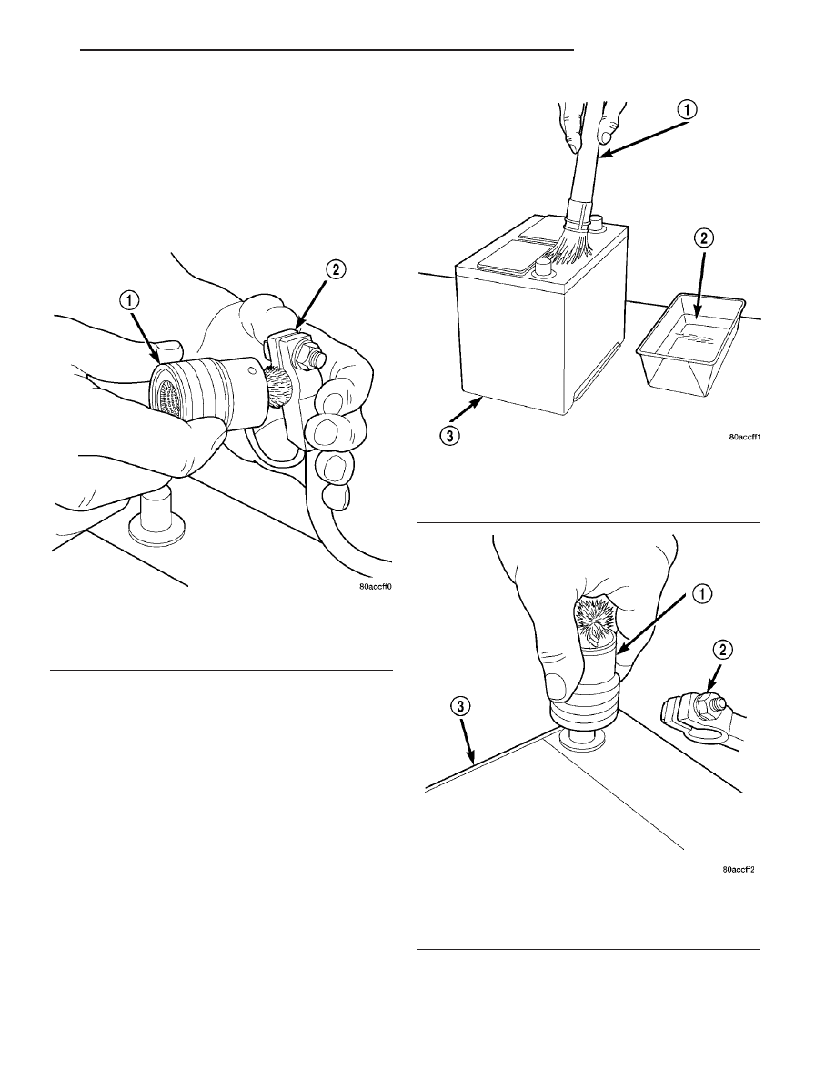
(1) Clean the battery cable terminal clamps of all

corrosion. Remove any corrosion using a wire brush
or a post and terminal cleaning tool, and a sodium
bicarbonate (baking soda) and warm water cleaning
solution (Fig. 1).

(2) Clean the battery tray and battery holddown

hardware of all corrosion. Remove any corrosion
using a wire brush and a sodium bicarbonate (baking
soda) and warm water cleaning solution. Paint any
exposed bare metal.

(3) If the removed battery is to be reinstalled,

clean the outside of the battery case and the top
cover with a sodium bicarbonate (baking soda) and
warm water cleaning solution using a stiff bristle
parts cleaning brush to remove any acid film (Fig. 2).
Rinse the battery with clean water. Ensure that the
cleaning solution does not enter the battery cells
through the vent holes.

(4) Clean the battery thermowrap with a sodium

bicarbonate (baking soda) and warm water cleaning
solution using a soft bristle parts cleaning brush to
remove any acid film.

(5) Clean any corrosion from the battery terminal

posts with a wire brush or a post and terminal
cleaner, and a sodium bicarbonate (baking soda) and
warm water cleaning solution (Fig. 3).

INSPECTION

The following information details the recommended

inspection procedures for the battery and related

Fig. 1 Cleaning Battery Cable Terminal Clamp -

Typical

1 - Terminal Brush
2 - Battery Cable

Fig. 2 Cleaning Battery - Typical

1 - Cleaning Brush
2 - Warm Water and Baking Soda Solution
3 - Battery

Fig. 3 Cleaning Battery Terminal Post - Typical

1 - Terminal Brush
2 - Battery Cable
3 - Battery

CS

BATTERY SYSTEM

8F - 5

BATTERY SYSTEM (Continued)

components. In addition to the maintenance sched-
ules found in this service manual and the owner’s
manual, it is recommended that these procedures be
performed any time the battery or related compo-
nents must be removed for vehicle service.

(1) Inspect the battery cable terminal clamps for

damage. Replace any battery cable that has a dam-
aged or deformed terminal clamp.

(2) Inspect the battery tray and battery holddown

hardware for damage. Replace any damaged parts.

(3) Slide the thermowrap off of the battery case.

Inspect the battery case for cracks or other damage
that could result in electrolyte leaks. Also, check the
battery terminal posts for looseness. Batteries with
damaged cases or loose terminal posts must be
replaced.

(4) Inspect the battery thermowrap for tears,

cracks, deformation or other damage. Replace any
battery thermal guard that has been damaged.

(5) Inspect the battery built-in test indicator sight

glass(if equipped) for an indication of the battery con-
dition. If the battery is discharged, charge as
required. Refer to Standard Procedures for the
proper battery built-in indicator test procedures. Also
refer to Standard Procedures for the proper battery
charging procedures.

SPECIFICATIONS

The battery Group Size number, the Cold Cranking

Amperage (CCA) rating, and the Reserve Capacity
(RC) rating or Ampere-Hours (AH) rating can be
found on the original equipment battery label. Be
certain that a replacement battery has the correct

Group Size number, as well as CCA, and RC or AH
ratings that equal or exceed the original equipment
specification for the vehicle being serviced. Battery
sizes and ratings are discussed in more detail below.

• Group Size - The outside dimensions and ter-

minal placement of the battery conform to standards
established by the Battery Council International
(BCI). Each battery is assigned a BCI Group Size
number to help identify a correctly-sized replace-
ment.

• Cold Cranking Amperage - The Cold Crank-

ing Amperage (CCA) rating specifies how much cur-
rent (in amperes) the battery can deliver for thirty
seconds at -18° C (0° F). Terminal voltage must not
fall below 7.2 volts during or after the thirty second
discharge period. The CCA required is generally
higher as engine displacement increases, depending
also upon the starter current draw requirements.

• Reserve Capacity - The Reserve Capacity (RC)

rating specifies the time (in minutes) it takes for bat-
tery terminal voltage to fall below 10.5 volts, at a
discharge rate of 25 amperes. RC is determined with
the battery fully-charged at 26.7° C (80° F). This rat-
ing estimates how long the battery might last after a
charging system failure, under minimum electrical
load.

• Ampere-Hours - The Ampere-Hours (AH) rat-

ing specifies the current (in amperes) that a battery
can deliver steadily for twenty hours, with the volt-
age in the battery not falling below 10.5 volts. This
rating is also sometimes identified as the twenty-
hour discharge rating.

BATTERY CLASSIFICATIONS & RATINGS

Part Number

BCI Group Size

Classification

Cold Cranking

Amperage

Reserve

Capacity

Ampere -

Hours

Load Test

Amperage

4686158AD

34

500

110 Minutes

60

250

8F - 6

BATTERY SYSTEM

CS

BATTERY SYSTEM (Continued)

SPECIAL TOOLS

BATTERY SYSTEM SPECIAL TOOLS

BATTERY

DESCRIPTION

Maintenance-free batteries are standard factory-in-

stalled equipment on this model. Male post type ter-
minals made of a soft lead material protrude from
the top of the molded plastic battery case (Fig. 4) to
provide the means for connecting the battery to the
vehicle electrical system. The battery positive termi-
nal post is visibly larger in diameter than the nega-
tive terminal post. The letters POS and NEG are
also molded into the top of the battery case adjacent
to their respective positive and negative terminal
posts for additional identification confirmation.

This battery is designed to provide a safe, efficient

and reliable means of storing electrical energy in a
chemical form. This means of energy storage allows
the battery to produce the electrical energy required
to operate the engine starting system, as well as to
operate many of the other vehicle accessory systems
for limited durations while the engine and/or the
charging system are not operating. The battery is
made up of six individual cells that are connected in
series. Each cell contains positively charged plate
groups that are connected with lead straps to the
positive terminal post, and negatively charged plate
groups that are connected with lead straps to the
negative terminal post. Each plate consists of a stiff
mesh framework or grid coated with lead dioxide

(positive plate) or sponge lead (negative plate). Insu-
lators or plate separators made of a non-conductive
material are inserted between the positive and nega-
tive plates to prevent them from contacting or short-
ing against one another. These dissimilar metal
plates are submerged in a sulfuric acid and water
solution called electrolyte.

The chemical composition of the metal coated

plates within the low-maintenance battery reduces
battery gassing and water loss, at normal charge and
discharge rates. Therefore, the battery should not
require additional water in normal service. However,
rapid loss of electrolyte can be caused by an over-
charging condition. Be certain to diagnose the charg-
ing system after replacing the battery for a low
electrolyte condition and before returning the vehicle
to service. Refer to Charging for additional informa-
tion.

The battery Group Size number, the Cold Cranking

Amperage (CCA) rating, and the Reserve Capacity
(RC) rating or Ampere-Hours (AH) rating can be
found on the original equipment battery label. Be
certain that a replacement battery has the correct
Group Size number, as well as CCA, and RC or AH
ratings that equal or exceed the original equipment
specification for the vehicle being serviced. Refer to
Battery Specifications in this group for the proper
factory-installed battery specifications.

Micro 420 Battery Tester

Fig. 4 Maintenance-Free Battery

1 - Positive Post
2 - Vent
3 - Cell Cap
4 - Vent
5 - Cell Cap
6 - Vent
7 - Negative Post
8 - Indicator Eye (if equipped)
9 - Electrolyte Level
10 - Plate Groups
11 - Maintenance-Free Battery

CS

BATTERY SYSTEM

8F - 7

BATTERY SYSTEM (Continued)

OPERATION

The battery is designed to store electrical energy in

a chemical form. When an electrical load is applied to
the terminals of the battery, an electrochemical reac-
tion occurs. This reaction causes the battery to dis-
charge electrical current from its terminals. As the
battery discharges, a gradual chemical change takes
place within each cell. The sulfuric acid in the elec-
trolyte combines with the plate materials, causing
both plates to slowly change to lead sulfate. At the
same time, oxygen from the positive plate material
combines with hydrogen from the sulfuric acid, caus-
ing the electrolyte to become mainly water. The
chemical changes within the battery are caused by
the movement of excess or free electrons between the
positive and negative plate groups. This movement of
electrons

produces

a

flow

of

electrical

current

through the load device attached to the battery ter-
minals.

As the plate materials become more similar chem-

ically, and the electrolyte becomes less acid, the volt-
age potential of each cell is reduced. However, by
charging the battery with a voltage higher than that
of the battery itself, the battery discharging process
is reversed. Charging the battery gradually changes
the sulfated lead plates back into sponge lead and
lead oxide, and the water back into sulfuric acid.
This action restores the difference in the electron
charges deposited on the plates, and the voltage
potential of the battery cells. For a battery to remain
useful, it must be able to produce high-amperage cur-
rent over an extended period. A battery must also be
able to accept a charge, so that its voltage potential
may be restored.

The battery is vented to release excess hydrogen

gas that is created when the battery is being charged
or discharged. However, even with these vents,
hydrogen gas can collect in or around the battery. If
hydrogen gas is exposed to flame or sparks, it may
ignite.

DIAGNOSIS AND TESTING - BATTERY

The battery must be completely charged and the

terminals should be properly cleaned and inspected
before diagnostic procedures are performed. Refer to
Battery System Cleaning for the proper cleaning pro-
cedures, and Battery System Inspection for the
proper battery inspection procedures. Refer to Stan-
dard Procedures for the proper battery charging pro-
cedures.

MICRO 420 BATTERY TESTER

The

Micro

420

automotive

battery

tester

is

designed to help the dealership technicians diagnose
the cause of a defective battery. Follow the instruc-
tion manual supplied with the tester to properly

diagnose a vehicle. If the instruction manual is not
available refer to the standard procedure in this sec-
tion, which includes the directions for using the
Micro 420 battery tester.

WARNING: IF THE BATTERY SHOWS SIGNS OF
FREEZING, LEAKING OR LOOSE POSTS, DO NOT
TEST, ASSIST-BOOST, OR CHARGE. THE BATTERY
MAY ARC INTERNALLY AND EXPLODE. PERSONAL
INJURY AND/OR VEHICLE DAMAGE MAY RESULT.

WARNING: EXPLOSIVE HYDROGEN GAS FORMS IN
AND AROUND THE BATTERY. DO NOT SMOKE,
USE FLAME, OR CREATE SPARKS NEAR THE BAT-
TERY. PERSONAL INJURY AND/OR VEHICLE DAM-
AGE MAY RESULT.

WARNING: THE BATTERY CONTAINS SULFURIC
ACID, WHICH IS POISONOUS AND CAUSTIC. AVOID
CONTACT WITH THE SKIN, EYES, OR CLOTHING.
IN THE EVENT OF CONTACT, FLUSH WITH WATER
AND CALL A PHYSICIAN IMMEDIATELY. KEEP OUT
OF THE REACH OF CHILDREN.

A battery that will not accept a charge is faulty,

and

must

be

replaced.

Further

testing

is

not

required. A fully-charged battery must be tested to
determine its condition. A battery that is fully-
charged, but does not pass the load test or Micro 420
test, is faulty and must be replaced.

NOTE: Completely discharged batteries may take
several hours to accept a charge.

STANDARD PROCEDURE

STANDARD PROCEDURE - CONVENTIONAL
BATTERY CHARGING

Battery charging is the means by which the bat-

tery can be restored to its full voltage potential. A
battery is fully-charged when:

• Micro 420 battery tester indicates battery is OK.

• Three hydrometer tests, taken at one-hour inter-

vals, indicate no increase in the temperature-cor-
rected specific gravity of the battery electrolyte.

• Passes Load Test

• Open-circuit voltage of the battery is 12.64 volts

or above.

WARNING: IF THE BATTERY SHOWS SIGNS OF
FREEZING, LEAKING, LOOSE POSTS, DO NOT
TEST, ASSIST-BOOST, OR CHARGE. THE BATTERY
MAY ARC INTERNALLY AND EXPLODE. PERSONAL
INJURY AND/OR VEHICLE DAMAGE MAY RESULT.

8F - 8

BATTERY SYSTEM

CS

BATTERY (Continued)


Content   ..  482  483  484  485   ..