Chrysler Pacifica. Manual - part 437
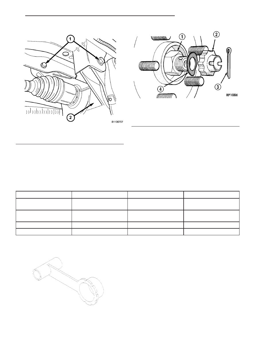
(6) Torque the halfshaft/hub nut to 244 N·m (180
ft.lbs.).
(7) Install the spring washer, nut lock, and a new
cotter pin (Fig. 10).
(8) Install wheel center cap.
(9) Check and adjust differential fluid level. (Refer
to 3 - DIFFERENTIAL & DRIVELINE/REAR DRIV-
ELINE MODULE/FLUID - STANDARD PROCE-
DURE)
SPECIFICATIONS - HALF SHAFT - REAR
TORQUE SPECIFICATIONS
DESCRIPTION
N·m
Ft. Lbs.
In. Lbs.
Bolt, Propeller Shaft-to-
Driveline Module
55
40
—
Bolt/Nut, Driveline
Module-to-Cradle
102
75
—
Nut, Hub
244
180
—
Nuts, Rear Wheel Lug
135
100
—
SPECIAL TOOLS
CV BOOT - INNER
REMOVAL
(1) Remove the half shaft requiring boot replace-
ment from the vehicle. (Refer to 3 - DIFFERENTIAL
& DRIVELINE/HALF SHAFT - REMOVAL)
(2) Remove large boot clamp which retains inner
tripod joint sealing boot to tripod joint housing and
discard.
(3) Remove small clamp which retains inner tripod
joint sealing boot to interconnecting shaft and dis-
card.
(4) Remove the sealing boot from the tripod hous-
ing and slide it down the interconnecting shaft.
Fig. 9 Module Mounting Bolts
1 - BOLT (2)
2 - DRIVELINE MODULE
Fig. 10 Cotter Pin, Nut Lock, And Spring Washer
1 - HUB NUT
2 - NUT LOCK
3 - COTTER PIN
4 - SPRING WASHER
Protector, 9099
CS
HALF SHAFT - REAR
3 - 17
HALF SHAFT - REAR (Continued)