Chrysler New Yorker. Manual - part 324
REAR DOOR LATCH
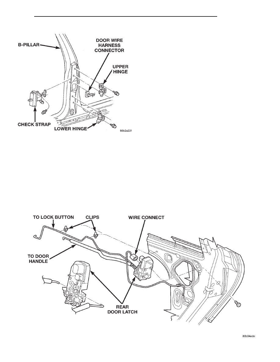
REMOVAL
(1) Close door glass.
(2) Remove door trim panel.
(3) Remove rear glass channel.
(4) Disconnect lock button link from door latch.
(5) Disconnect outside door handle link from door
latch.
(6) Remove screws attaching door latch to door end
frame (Fig. 81).
(7) Remove latch from door.
INSTALLATION
(1) Place latch in position in door.
(2) Install screws attaching door latch to door end
frame.
(3) Connect outside door handle link to door latch.
(4) Connect lock button link to door latch.
(5) Install rear glass channel.
(6) Verify door latch operation.
(7) Install door trim panel.
REAR DOOR LATCH STRIKER
REMOVAL
(1) Open rear door.
(2) Mark location of door latch striker on C-pillar
to assist installation alignment.
(3) Remove bolts holding striker to C-pillar (Fig.
82).
(4) Remove door latch striker from vehicle.
INSTALLATION
(1) Place door latch striker in position on vehicle.
(2) Install bolts to hold striker to C-pillar.
(3) Align striker to marked location on C-pillar
and tighten bolts.
(4) Verify alignment and operation of door, adjust
as necessary.
Fig. 80 Rear Door Hinge
Fig. 81 Rear Door Latch
300M
BODY
23 - 37
REMOVAL AND INSTALLATION (Continued)