Chrysler New Yorker. Manual - part 28


  Index      Chrysler     Chrysler New Yorker - service repair manual 1997-1999 year


Search            


Content   ..  26  27  28  29   ..


Chrysler New Yorker. Manual - part 28


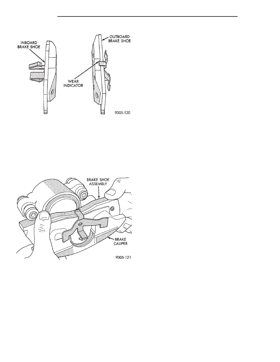
NOTE: When installing inboard brake shoe into cal-
iper piston, be sure brake shoe is positioned
squarely against the face of the caliper piston.

(4) Install the new inboard brake shoe assembly

into the caliper piston by firmly pressing it into bore
of caliper piston with thumbs (Fig. 35).

(5) Slide the new outboard brake shoe assembly

onto the caliper assembly (Fig. 37).

(6) Install shoe retractor clips between outboard

and inboard shoes, at both ends of shoe backing
plates (Fig. 38).

(7) Reinstall caliper as described in Front Disc

Brake Caliper Removal and Installation, found else-
where in this section of this service manual.

CAUTION: Before vehicle is moved after performing
a service procedure on the vehicle brake system,
pump the brake pedal several times to insure the
vehicle has a firm brake pedal that is to adequate to
stop the vehicle.

(8) Road test the vehicle and make several stops to

wear off any foreign material on the brakes and to
seat the brake shoe linings.

REAR DISC BRAKE CALIPER

During service procedures, grease or any other for-

eign material must be kept off brake shoe assem-
blies, and braking surfaces of rotor.

Handling of the rotor and caliper, must be done in

such a way as to avoid damage to the rotor and
scratching or nicking of lining on the brake shoes.

If inspection reveals that the caliper piston seal is

leaking, it MUST be replaced immediately.

During removal and installation of a wheel and

tire assembly, use care not to strike the caliper.

REMOVE

(1) Raise vehicle on jackstands or centered on a

hoist. See Hoisting in the Lubrication and Mainte-
nance section of this manual.

(2) Remove rear wheel and tire assemblies from

vehicle.

(3) Remove the 2 caliper assembly to adapter

guide pin bolts (Fig. 39).

(4) Remove caliper from adapter using following

procedure. First rotate top of caliper away from
adapter. Then lift the caliper off the bottom abut-
ment on the adapter (Fig. 40).

(5) Support caliper assembly firmly from rear strut

to prevent weight of caliper from damaging the flex-
ible brake hose (Fig. 41).

(6) Remove the rear rotor from hub by pulling it

straight off the wheel mounting studs (Fig. 42).

INSTALL

NOTE:

Step 1 below is only required when install-

ing the disc brake caliper after new brake shoes
have been installed.

(1) Completely retract caliper piston back into pis-

ton bore of caliper assembly.

(2) Lubricate both adapter abutments with a lib-

eral amount of Mopar

t Multipurpose Lubricant, or

equivalent.

(3) Install the rear rotor on the hub, making sure

it is squarely seated on the face of the hub (Fig. 42).

CAUTION:

Use care when installing the caliper

assembly onto the adapter, so the caliper guide pin
bushings do not get damaged by the mounting
bosses.

(4) Carefully lower caliper and brake shoes over

rotor and onto the adapter using the reverse proce-
dure for removal (Fig. 40).

Fig. 36 Front Brake Shoe Assembly Identification

Fig. 37 Installing Outboard Brake Shoe Assembly

5 - 26

BRAKES

300M

REMOVAL AND INSTALLATION (Continued)

CAUTION: When installing guide pin bolts extreme
caution should be taken not to crossthread the cal-
iper guide pin bolts.

(5) Install the caliper guide pin bolts. Tighten the

guide pin bolts to a torque of 22 N·m (192 in. lbs.).

(6) Install the wheel and tire assembly.
(7) Tighten the wheel mounting stud nuts in

proper sequence until all nuts are torqued to half

specification. Then repeat the tightening sequence to
the full specified torque of 129 N·m (95 ft. lbs.).

(8) Remove jackstands or lower hoist.

CAUTION: Before moving vehicle, pump the brake
pedal several times to insure the vehicle has a firm
brake pedal to adequately stop vehicle.

(9) Road test the vehicle and make several stops to

wear off any foreign material on the brakes and to
seat the brake shoe linings.

Fig. 38 Front Disc Brake Caliper Assembly

Fig. 39 Removing Caliper Guide Pin Bolts

Fig. 40 Removing / Installing Caliper Assembly

300M

BRAKES

5 - 27

REMOVAL AND INSTALLATION (Continued)

REAR DISC BRAKE SHOES

WARNING:

ALTHOUGH

FACTORY

INSTALLED

BRAKE LININGS ARE MADE FROM ASBESTOS
FREE MATERIALS, SOME AFTER MARKET BRAKE
LININGS MAY CONTAIN ASBESTOS. THIS SHOULD
BE TAKEN INTO ACCOUNT WHEN SERVICING A
VEHICLE’S BRAKE SYSTEM, WHEN AFTERMARKET
BRAKE LININGS MAY HAVE BEEN INSTALLED ON
THE VEHICLE. ALWAYS WEAR A RESPIRATOR
WHEN

CLEANING

BRAKE

COMPONENTS,

AS

ASBESTOS CAN CAUSE SERIOUS BODILY HARM
SUCH AS ASBESTOSIS AND OR CANCER. NEVER
CLEAN BRAKE COMPONENTS BY USING COM-
PRESSED AIR, USE ONLY A VACUUM CLEANER
SPECIFICALLY DESIGNED FOR THE REMOVAL OF
BRAKE DUST. IF A VACUUM CLEANER IS NOT
AVAILABLE, CLEAN BRAKE PARTS USING ONLY
WATER DAMPENED SHOP TOWELS. DO NOT CRE-
ATE BRAKE LINING DUST BY SANDING BRAKE
LININGS WHEN SERVICING A VEHICLE. DISPOSE
OF ALL DUST AND DIRT SUSPECTED OF CONTAIN-
ING ASBESTOS FIBERS USING ONLY SEALED AIR-
TIGHT

BAGS

OR

CONTAINERS.

FOLLOW ALL

RECOMMENDED

SAFETY

PRACTICES

PRE-

SCRIBED BY THE OCCUPATIONAL SAFETY AND
HEALTH ADMINISTRATION (OSHA) AND THE ENVI-
RONMENTAL PROTECTION AGENCY (EPA), FOR
HANDLING AND DISPOSAL OF PRODUCTS CON-
TAINING ASBESTOS.

During service procedures, grease or any other for-

eign material must be kept off brake shoe assem-
blies, and braking surfaces of brake drum and
external surfaces of hub/bearing assembly.

Handling of the braking disc (rotor) and caliper

should be done in such a way as to avoid deformation
of the disc and scratching or nicking of brake linings.

If inspection reveals that the square sectioned cal-

iper piston seal is worn or damaged, it MUST be
replaced immediately.

During removal and installation of a wheel and

tire assembly, use care not to strike the caliper.

REMOVE

(1) Raise vehicle on jackstands or centered on a

hoist. See Hoisting in the Lubrication and Mainte-
nance section of this manual.

Fig. 41 Storing Caliper

Fig. 42 Removing / Installing Rear Rotor

5 - 28

BRAKES

300M

REMOVAL AND INSTALLATION (Continued)

(2) Remove rear wheel and tire assemblies from

vehicle.

(3) Remove the 2 caliper assembly to adapter

guide pin bolts (Fig. 43).

(4) Remove caliper from adapter using the follow-

ing procedure. First rotate top of caliper away from
adapter. Then lift caliper assembly off bottom abut-
ment of adapter to remove it from the vehicle (Fig.
44).

(5) Support caliper assembly firmly from rear strut

to prevent weight of caliper from damaging the flex-
ible brake hose (Fig. 45).

(6) Remove the rear rotor from the hub by pulling

it straight off the wheel mounting studs (Fig. 46).

(7) Remove outboard brake shoe, by prying brake

shoe retaining clip over raised area on caliper and
sliding the shoe off the caliper (Fig. 47).

(8) Pull inboard brake shoe away from piston,

until the retaining clip is free from the cavity in the
piston (Fig. 48).

CALIPER INSPECTION

Check for piston seal leaks (brake fluid in and

around boot area and inboard lining) and for any
ruptures of the piston dust boot. If boot is damaged,
or fluid leak is visible, disassemble caliper assembly
and install a new seal and boot, (and piston if
scored). Refer to procedures titled Disc Brake Caliper
Disassembly.

Fig. 43 Caliper Guide Pin Bolts

Fig. 44 Removing / Installing Caliper

Fig. 45 Storing Caliper

Fig. 46 Removing / Installing Rear Rotor

300M

BRAKES

5 - 29

REMOVAL AND INSTALLATION (Continued)


Content   ..  26  27  28  29   ..