Chrysler 300M, Dodge Interpid. Manual - part 340


  Index      Chrysler     Chrysler 300M / Concorde / Interpid / LHS, Dodge Interpid - service repair manual 2000-2004 year


Search            


Content   ..  338  339  340  341   ..


Chrysler 300M, Dodge Interpid. Manual - part 340


INSTALLATION

NOTE: Before reinstalling a tire pressure sensor,
replace sealing grommet at base of valve stem.

(1) Wipe area clean where sensor sealing grommet

contacts wheel. Make sure surface of wheel is not
damaged.

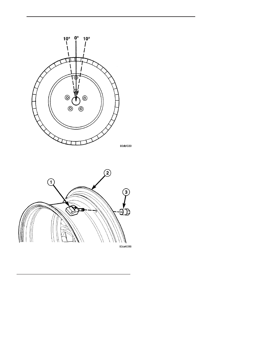
(2) Install sensor in wheel as shown (Fig. 19). Do

not attempt to mount sensor otherwise, damage may
occur.

(3) Using a thin wall socket, install special sensor

nut (Fig. 19). Tighten nut to 4 N·m (35 in. lbs.)
torque.

CAUTION: Over-torquing the sensor nut by as little
as 12 N·m (106 in. lbs.) may result in sensor sepa-
ration from the valve stem. Under this condition,
the sensor may still function, however, the condi-
tion should be corrected immediately.

(4) Mount tire on wheel following tire changer

manufacturers instructions, paying special attention
to the following to avoid damaging tire pressure sen-
sor:

(a) Rotating Wheel Tire Changers- Once the

wheel is mounted to the changer, position the sen-
sor valve stem approximately 210° from the head
of the changer in a clockwise direction before rotat-
ing the wheel (also in a clockwise direction) to
mount the tire (Fig. 20). Use this procedure on
both the upper and lower tire beads.

(b) Rotating Tool Tire Changers - Position the

wheel on the changer so that the sensor valve stem
is located approximately 210° clockwise from the
installation end of the mounting/dismounting tool
once the tool is mounted for tire installation (Fig.
21). Make sure the sensor is clear of the lower
bead breaker area to avoid damaging the sensor
when the breaker rises (Fig. 21). Rotate the tool in
a counterclockwise direction to mount the tire. Use
this procedure on both the upper and lower tire
beads.
(5) Install wheel and tire assembly on vehicle.

(Refer to 22 - TIRES/WHEELS - INSTALLATION)

(6) Retrain tire pressure sensors. (Refer to 22 -

TIRES/WHEELS/TIRE PRESSURE MONITORING/
SENSOR - STANDARD PROCEDURE)

Fig. 18 Start Mount/Dismount Tool Within 10

Degrees Of Valve Stem

Fig. 19 Sensor Mounting To Wheel

1 - TIRE PRESSURE SENSOR
2 - WHEEL
3 - NUT

LH

TIRES/WHEELS

22 - 13

SENSOR - TPM (Continued)

TIRES

DESCRIPTION

DESCRIPTION - TIRE

Tires are designed and engineered for each specific

vehicle. They provide the best overall performance
for normal operation. The ride and handling charac-
teristics match the vehicle’s requirements. With
proper care they will give excellent reliability, trac-
tion, skid resistance, and tread life.

Driving habits have more effect on tire life than

any other factor. Careful drivers will obtain, in most
cases, much greater mileage than severe use or care-
less drivers. A few of the driving habits which will
shorten the life of any tire are:

• Rapid acceleration

• Severe application of brakes

• High-speed driving

• Taking turns at excessive speeds

• Striking curbs and other obstacles

• Operating vehicle with over or under inflated

tire pressures

Radial ply tires are more prone to irregular tread

wear. It is important to follow the tire rotation inter-
val shown in the section on Tire Rotation. This will
help to achieve a greater tread-life potential.

TIRE IDENTIFICATION

Tire type, size, load index and speed rating are

encoded in the letters and numbers imprinted on the
side wall of the tire. Refer to the Tire Identification
chart to decipher the code. For example purposes, the
tire size P225/60 R 16 97 T is used in the chart. An
All Season type tire will also have either M + S, M &
S or M - S (indicating mud and snow traction)
imprinted on the side wall. An Extra or Light Load
marking “XL” or “LL” may also be listed on the side-
wall. The absence of an “XL” or “LL” marking infers
a standard load tire.

Fig. 20 Mounting Tire Using Rotating Wheel

Machine

1 - HEAD OF CHANGER LOCATED HERE
2 - VALVE STEM

Fig. 21 Mounting Tire Using Rotating Tool Machine

1 - VALVE STEM
2 - INSTALLATION END OF MOUNTING/DISMOUNTING TOOL
3 - BEAD BREAKER (KEEP CLEAR OF SENSOR)

22 - 14

TIRES/WHEELS

LH

SENSOR - TPM (Continued)

TIRE IDENTIFICATION

P

TIRE TYPE (Not

present on all tires)

P - Passenger

T - Temporary

C - Commercial

LT - Light Truck

225

SECTIONAL WIDTH

SHOWN IN
MILLIMETERS

60

ASPECT RATIO

SECTIONAL HEIGHT
÷ SECTIONAL WIDTH
(Refer to Aspect Ratio
Figure 22 )

R

CONSTRUCTION

TYPE

R - RADIAL

B - BIAS BELTED

D - DIAGONAL (BIAS)

16

WHEEL DIAMETER

SHOWN IN INCHES

97

LOAD INDEX

*

T

SPEED RATING

*

* NOTE: Consult the tire manufacturer regarding
any questions on tire specifications or capabilities.

TIRE CHAINS

Refer to the owners manual supplied with the vehi-

cle to determine whether the use of tire chains is per-
mitted on this vehicle.

DESCRIPTION - RADIAL-PLY TIRES

Radial-ply tires improve handling, tread life and

ride quality, and decrease rolling resistance.

Radial-ply tires must always be used in sets of

four. Under no circumstances should they be used on
the front only. They may be mixed with temporary
spare tires when necessary. A maximum speed of 80
km/h (50 mph) is recommended while a temporary
spare is in use.

Radial-ply tires have the same load-carrying capac-

ity as other types of tires of the same size. They also
use the same recommended inflation pressures.

The use of oversized tires, either in the front or

rear of the vehicle, can cause vehicle drive train fail-
ure. This could also cause inaccurate wheel speed
signals when the vehicle is equipped with Antilock
Brakes.

The use of tires from different manufactures on the

same vehicle is NOT recommended. The proper tire
pressure should be maintained on all four tires.

DESCRIPTION - REPLACEMENT TIRES

WARNING: FAILURE TO EQUIP THE VEHICLE WITH
TIRES HAVING ADEQUATE SPEED CAPABILITY
CAN RESULT IN SUDDEN TIRE FAILURE.

WARNING:: IN ORDER TO MAINTAIN THE SPEED
CAPABILITY OF THE VEHICLE, REPLACEMENT
TIRES MUST HAVE SPEED RATINGS EQUAL TO OR
HIGHER THAN THOSE FITTED TO THE VEHICLE AS
ORIGINAL EQUIPMENT. IF TIRES WITH LOWER
SPEED RATINGS ARE FITTED, THE VEHICLE’S
HANDLING MAY BE AFFECTED AND THE SPEED
CAPABILITY OF THE VEHICLE MAY BE LOWERED
TO THE MAXIMUM SPEED CAPABILITY OF THE
REPLACEMENT TIRES. TO AVOID AN ACCIDENT
RESULTING IN SEVERE OR FATAL INJURY, CON-
SULT THE TIRE MANUFACTURER IN REGARDS TO
MAXIMUM SPEED RATINGS.

It is recommended that tires equivalent to the orig-

inal equipment tires be used when replacement is
needed.

Failure to use equivalent replacement tires may

adversely affect the safety and handling of the vehi-
cle.

The original equipment tires provide a proper com-

bination of many characteristics such as:

• Ride

• Noise

• Handling

• Durability

• Tread life

• Traction

• Rolling resistance

• Speed capability

Fig. 22 Tire Aspect Ratio

1 - SECTIONAL WIDTH
2 - SECTIONAL HEIGHT

LH

TIRES/WHEELS

22 - 15

TIRES (Continued)

The use of tires smaller than the minimum tire

size approved for the vehicle can result in tire over-
loading and failure.

Use tires that have the approved load rating for

the vehicle and never overload them. Failure to equip
the vehicle with tires having adequate speed capabil-
ity can result in sudden tire failure and loss of vehi-
cle control.

The use of oversize tires may cause interference

with vehicle components. Under extremes of suspen-
sion and steering travel, interference with vehicle
components may cause tire damage.

DESCRIPTION - SPARE TIRE (TEMPORARY)

The compact temporary spare tire is designed for

emergency use only. The original tire should be
repaired or replaced at the first opportunity, then
reinstalled. Do not exceed speeds of 80 km/h (50
mph) when using the temporary spare tire. Refer to
Owner’s Manual for complete details.

DIAGNOSIS AND TESTING

DIAGNOSIS AND TESTING - TIRE NOISE

Unusual tire noise can be associated with tire and

wheel vibration or irregular tire wear. For vibration,
(Refer to 22 - TIRES/WHEELS - DIAGNOSIS AND
TESTING). For irregular tire wear, (Refer to 22 -
TIRES/WHEELS/TIRES - DIAGNOSIS AND TEST-
ING).

DIAGNOSIS AND TESTING - TIRE/VEHICLE
LEAD

(Refer to 2 - SUSPENSION/WHEEL ALIGNMENT

- DIAGNOSIS AND TESTING)

DIAGNOSIS AND TESTING - TIRE WEAR
PATTERNS

Under inflation will cause wear on the shoulders of

tire. Over inflation will cause wear at the center of
tire.

Excessive camber causes the tire to run at an

angle to the road. One side of tread is then worn
more than the other (Fig. 23).

Excessive toe-in or toe-out causes wear on the

tread edges and a feathered effect across the tread
(Fig. 23).

DIAGNOSIS AND TESTING - TREAD WEAR
INDICATORS

Tread wear indicators are molded into the bottom

of the tread grooves. When tread depth is 1.6 mm
(1/16 in.), the tread wear indicators will appear as a
13 mm (1/2 in.) band (Fig. 24).

Tire replacement is necessary when indicators

appear in two or more grooves or if localized balding
occurs.

Fig. 23 Tire Wear Patterns

22 - 16

TIRES/WHEELS

LH

TIRES (Continued)


Content   ..  338  339  340  341   ..