Chrysler 300M, Dodge Interpid. Manual - part 73


  Index      Chrysler     Chrysler 300M / Concorde / Interpid / LHS, Dodge Interpid - service repair manual 2000-2004 year


Search            


Content   ..  71  72  73  74   ..


Chrysler 300M, Dodge Interpid. Manual - part 73


STARTER MOTOR RELAY

DESCRIPTION

The Starter Relay is a micro relay located in the

Power Distribution Center (PDC), positioned in the
left front corner of the engine compartment.

OPERATION

As battery power is applied to the relay from the

ignition switch, battery power is applied to the
starter motor through the relay to the starter sole-
noid.

DIAGNOSIS AND TESTING - STARTER RELAY

WARNING: CHECK TO ENSURE THAT THE TRANS-
MISSION IS IN THE PARK POSITION/NEUTRAL
WITH THE PARKING BRAKE APPLIED

The starter relay is located in the Power Distribu-

tion Center (PDC) in the engine compartment. Refer
to the PDC label for relay identification and location.

Remove

the

starter

relay

from

the

PDC

as

described in this group to perform the following tests.
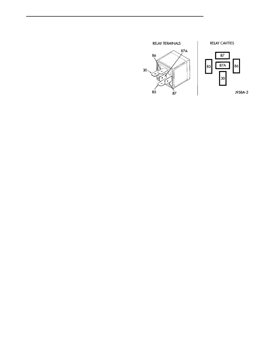
Refer to Starter Relay Chart for terminal numbers
and locations.

(1) A relay in the de-energized position should

have continuity between terminals 87A and 30, and
no continuity between terminals 87 and 30. If OK, go
to Step 2. If not OK, replace the faulty relay.

(2) Resistance between terminals 85 and 86 (elec-

tromagnet) should be 75 ±5 ohms. If OK, go to Step
3. If not OK, replace the faulty relay.

(3) Connect a battery B+ lead to terminals 86 and

a ground lead to terminal 85 to energize the relay.
The relay should click. Also test for continuity
between terminals 30 and 87, and no continuity
between terminals 87A and 30. If OK, refer to
Starter Relay Circuit Test procedure. If not OK,
replace the faulty relay.

STARTER RELAY CIRCUIT TEST

(1) The relay common feed terminal cavity (30) is

connected to battery voltage and should be hot at all
times. If OK, go to Step 2. If not OK, repair the open
circuit to the PDC fuse as required.

(2) The relay normally closed terminal (87A) is

connected to terminal 30 in the de-energized position,
but is not used for this application. Go to Step 3.

(3) The relay normally open terminal (87) is con-

nected to the common feed terminal (30) in the ener-

gized position. This terminal supplies battery voltage
to the starter solenoid field coils. There should be
continuity between the cavity for relay terminal 87
and the starter solenoid terminal at all times. If OK,
go to Step 4. If not OK, repair the open circuit to the
starter solenoid as required.

(4) The coil battery terminal (86) is connected to

the electromagnet in the relay. It is energized when
the ignition switch is held in the Start position.
Check for battery voltage at the cavity for relay ter-
minal 86 with the ignition switch in the Start posi-
tion, and no voltage when the ignition switch is
released to the On position. If OK, go to Step 5. If
not OK, check for an open or short circuit to the igni-
tion switch and repair, if required. If the circuit to
the ignition switch is OK, refer to the Ignition Switch
Test procedure in this group.

(5) The coil ground terminal (85) is connected to

the electromagnet in the relay. The relay is grounded
through Pin 8 of the PCM, when the gear selector
lever is in the Park or Neutral position. Check for
continuity to ground at the cavity for relay terminal
85, when the gear selector lever is in the Park or
Neutral position. If not OK, check for an open circuit
to Pin 8 of the PCM and from Pin 76 of the PCM to
transmission range sensor. Repair as necessary. If
both circuits are OK, refer to the Transmission
Range Sensor Test in Transaxle. If the Transmission
Range Sensor test OK, and all other tests are OK,
replace the PCM.

REMOVAL

The relay is located in the Power Distribution Cen-

ter (PDC). Refer to the PDC cover for relay location.

STARTER RELAY CHART

LH

STARTING

8F - 29

STARTER SOLENOID

DESCRIPTION

The Starter Solenoid is mounted directly to the

Starter Motor, mounted on the left side of the engine.

OPERATION

The Starter Solenoid is a switching device used to

activate the high amperage starter motor circuit from
a low amperage control circuit.

DIAGNOSIS AND TESTING - STARTER
SOLENOID

WARNING: CHECK TO ENSURE THAT THE TRANS-
MISSION IS IN THE PARK POSITION WITH THE
PARKING BRAKE APPLIED

(1) Verify battery condition. Battery must be in

good condition with a full charge before performing
any starter tests. Refer to Battery Tests.

(2) Perform Starter Solenoid test BEFORE per-

forming the starter relay test.

(3) Raise the vehicle.
(4) Perform a visual inspection of the starter/

starter solenoid for corrosion, loose connections or
faulty wiring.

(5) Lower the vehicle.
(6) Locate and remove the starter relay from the

Power Distribution Center (PDC). Refer to the PDC
label for relay identification and location.

(7) Connect a remote starter switch or a jumper

wire between the remote battery positive post and
terminal 87 of the starter relay connector.

(a) If engine cranks, starter/starter solenoid is

good. Go to the Starter Relay Test.

(b) If engine does not or solenoid chatters, check

wiring and connectors from starter relay to starter
solenoid for loose or corroded connections. Particu-
larly at starter terminals.

(c) Repeat test. If engine still fails to crank prop-

erly, trouble is within starter or starter mounted
solenoid, and replace starter.

8F - 30

STARTING

LH

HEATED SYSTEMS

TABLE OF CONTENTS

page

page

HEATED GLASS . . . . . . . . . . . . . . . . . . . . . . . . . . . 1
HEATED MIRRORS . . . . . . . . . . . . . . . . . . . . . . . . . 8

HEATED SEAT SYSTEM . . . . . . . . . . . . . . . . . . . . . 9

HEATED GLASS

TABLE OF CONTENTS

page

page

HEATED GLASS

DESCRIPTION - WINDOW DEFOGGER

. . . . . . . 1

OPERATION - WINDOW DEFOGGER

. . . . . . . . . 2

DIAGNOSIS AND TESTING

DIAGNOSIS AND TESTING - WINDOW

DEFOGGER . . . . . . . . . . . . . . . . . . . . . . . . . . 2

DIAGNOSIS AND TESTING - SYSTEM TEST

. . 2

DIAGNOSIS AND TESTING - FUSE AND

ELECTRICAL SHORT TEST . . . . . . . . . . . . . . . 3

REAR WINDOW DEFOGGER GRID

DIAGNOSIS AND TESTING - REAR WINDOW

DEFOGGER GRID

. . . . . . . . . . . . . . . . . . . . . . 3

STANDARD PROCEDURE - REAR WINDOW

DEFOGGER GRID REPAIR

. . . . . . . . . . . . . . . 4

REAR WINDOW DEFOGGER RELAY

DESCRIPTION

. . . . . . . . . . . . . . . . . . . . . . . . . . 5

OPERATION

. . . . . . . . . . . . . . . . . . . . . . . . . . . . 5

DIAGNOSIS AND TESTING - REAR WINDOW

DEFOGGER RELAY

. . . . . . . . . . . . . . . . . . . . . 5

REMOVAL

. . . . . . . . . . . . . . . . . . . . . . . . . . . . . 6

INSTALLATION

. . . . . . . . . . . . . . . . . . . . . . . . . . 6

REAR WINDOW DEFOGGER SWITCH

DESCRIPTION

. . . . . . . . . . . . . . . . . . . . . . . . . . 7

OPERATION

. . . . . . . . . . . . . . . . . . . . . . . . . . . . 7

DIAGNOSIS AND TESTING - REAR WINDOW

DEFOGGER SWITCH

. . . . . . . . . . . . . . . . . . . 7

REMOVAL

. . . . . . . . . . . . . . . . . . . . . . . . . . . . . 7

HEATED GLASS

DESCRIPTION - WINDOW DEFOGGER

The

Rear

Window

Defogger

electrical

system

involves the operation of the Manual Temperature
Control (MTC) or Automatic Temperature Control
(ATC) head, the Body Control Module (BCM), and
the rear window defogger relay and wiring. The sys-
tem consists of a rear glass with two vertical bus
bars and a series of electrically connected grid lines
fired on the inside surface. The Body Control Module
(BCM) operates a relay located in the right side
trunk area on all models (Fig. 1).

Vehicles with Rear Window Antenna refer to Audio

Systems.

Vehicles equipped with an electrically heated rear

window defogger also have a 90 amp generator.

LH

HEATED SYSTEMS

8G - 1

OPERATION - WINDOW DEFOGGER

The passenger can push the Rear Widow Defogger

button on the MTC or ATC head to defog the rear
glass (Fig. 2). The system will only operate when the
ignition switch is in the run position. Once the Rear
Widow Defogger button is pushed, the button indica-
tor will light and the system will operate for a period
of time and then automatically turn off. Refer to the
owner’s manual for operation of the MTC or ATC sys-
tem.

When the rear window defogger relay is ON, cur-

rent is directed to the rear defogger grid lines. The
heated grid lines heat the rear glass to clear the sur-
face of fog or frost.

Circuit protection is provided by a fusible link,

located in the charging circuit, for the heated grid
circuit and by a fuse for the relay control circuit.

The MTC or the ATC head sends a signal to the

BCM, which indicates to the BCM that the operator
wants the rear window grid to heat. An output wire
from the BCM connects to the coil of the rear window
defogger relay. The other side of the coil is connected
to a fuse. The BCM turns on the relay by connecting
the output line of the BCM to vehicle ground. The
relay contacts will then close supplying vehicle power
to the rear window defogger grid.

CAUTION: Grid lines can be damaged or scraped
off with sharp instruments, care should be taken in
cleaning

glass

or

removing

foreign

materials,

decals or stickers. Normal glass cleaning solvents
or hot water used with rags or toweling is recom-
mended.

DIAGNOSIS AND TESTING

DIAGNOSIS AND TESTING - WINDOW
DEFOGGER

Electrically Heated Rear Window Defogger opera-

tion can be easily checked in three steps:

(1) Use ATC or MTC self diagnostics, or the DRB

III

t scan tool to check fault codes and control button

operation. (Refer to 24 - HEATING & AIR CONDI-
TIONING - DIAGNOSIS AND TESTING - SELF
DIAGNOSTICS) Note, this does not check the EBL
system. There are no fault codes that can check for
the EBL grid, relay, or wiring. Refer to steps 2 and 3
for system tests.

(2) Perform a system test with a voltmeter. (Refer

to 8 - ELECTRICAL/HEATED GLASS - DIAGNOSIS
AND TESTING - SYSTEM TEST)

(3) Check the voltages at the rear grid relay.

(Refer to 8 - ELECTRICAL/HEATED GLASS/REAR
WINDOW DEFOGGER RELAY - DIAGNOSIS AND
TESTING)

DIAGNOSIS AND TESTING - SYSTEM TEST

(1) Start the engine. With the engine running,

push the Rear Window Defogger button on the ATC
or MTC head. The button LED indicator should light.
If the EBL indicator does not light on the MTC
HEAD, 
then there may be a wiring problem. This
may also indicate that the BCM will not complete the
circuit to ground that is required to energize the EBL
relay coil (non-ATC vehicles only). (Refer to 8 -
ELECTRICAL/HEATED

GLASS/REAR

WINDOW

DEFOGGER RELAY - DIAGNOSIS AND TESTING)
On ATC vehicles, the LED indicator may light when

Fig. 1 REAR WINDOW DEFOGGER SYSTEM

SCHEMATIC

1 - BCM AND BUTTON LED RELAY CONTROL LINE (MANUAL
TEMPERATURE CONTROL ONLY)
2 - VEHICLE VOLTAGE SUPPLY
3 - GROUND CONNECTOR
4 - REAR WINDOW GRID LINE STRUCTURE
5 - POINT B
6 - MIDPOINT C (TYPICAL)
7 - POINT A
8 - POWER CONNECTOR

Fig. 2 ATC CONTROL HEAD

8G - 2

HEATED GLASS

LH

HEATED GLASS (Continued)


Content   ..  71  72  73  74   ..