Chrysler 300M, Dodge Interpid. Manual - part 65


  Index      Chrysler     Chrysler 300M / Concorde / Interpid / LHS, Dodge Interpid - service repair manual 2000-2004 year


Search            


Content   ..  63  64  65  66   ..


Chrysler 300M, Dodge Interpid. Manual - part 65


(4) Select Quick Learn Procedure. Follow the

instructions of the DRB to perform the Quick Learn
Procedure.

REMOVAL

USE THE DRBIII

SCAN TOOL TO REPRO-

GRAM THE NEW PCM WITH THE VEHICLES
ORIGINAL IDENTIFICATION NUMBER (VIN)
AND THE VEHICLES ORIGINAL MILEAGE. IF
THIS STEP IS NOT DONE A DIAGNOSTIC
TROUBLE CODE (DTC) MAY BE SET.

The PCM engine control strategy prevents reduced

idle speeds until after the engine operates for 320 km
(200 miles). If the PCM is replaced after 320 km (200
miles) of usage, update the mileage and vehicle iden-
tification number (VIN) in the new PCM. Use the
DRBIII

t scan tool to change the mileage and VIN in

the PCM. If this step is not done a diagnostic trouble
code (DTC) may be set and SKIM must be done or
car will not start if it is a SKIM equipped car. If a
SKIM car you must do a secret key transfer also.
Refer to the appropriate Powertrain Diagnostic Man-
ual and the DRBIII

t scan tool.

To avoid possible voltage spike damage to PCM,

ignition key must be off, and the negative battery
cable must be disconnected before unplugging the
PCM connectors. Note radio programs.

(1) Unbolt the washer bottle filler neck and repo-

sition.

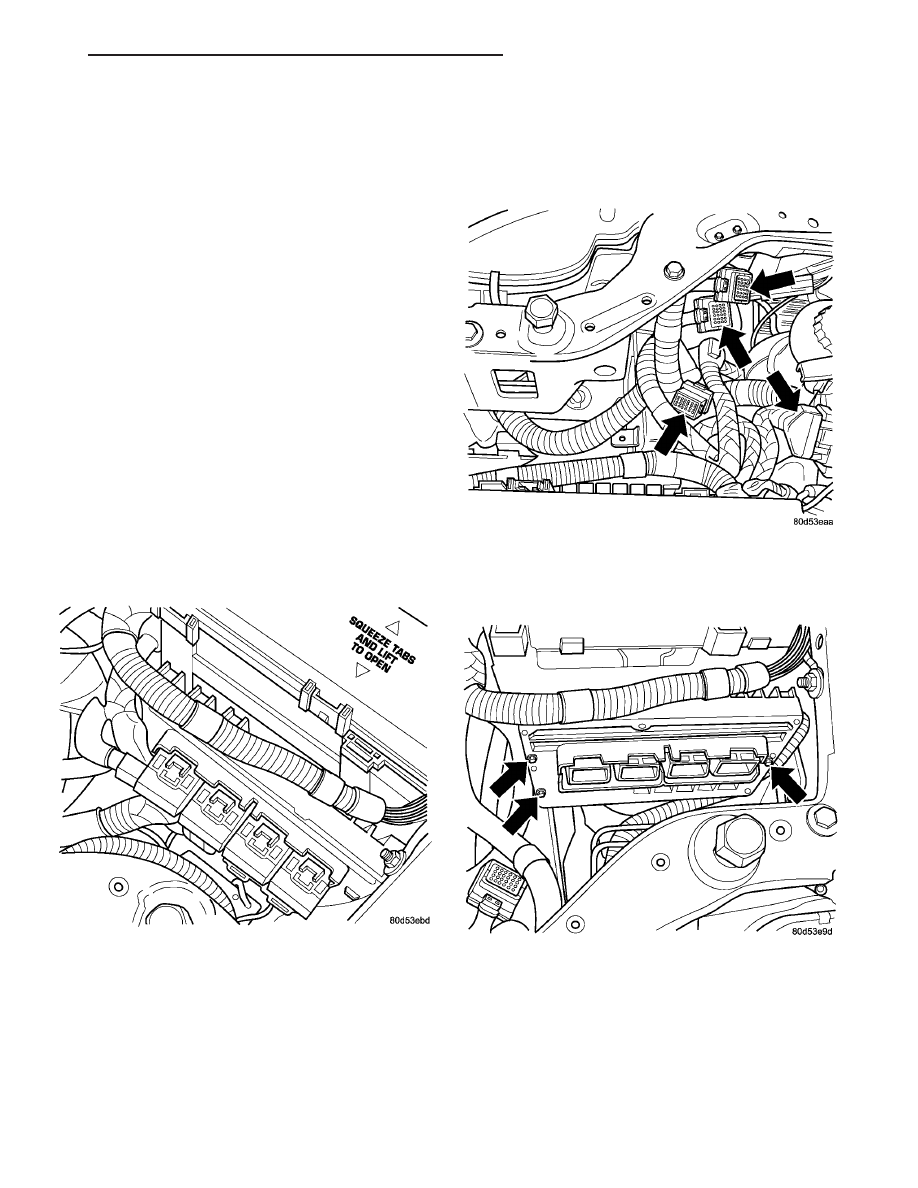
(2) Disconnect the 4 PCM electrical connector.
(3) Reposition wiring harness out of the way (Fig.

7).

(4) Remove the 3 fasteners from PCM mounting

(Fig. 8).

NGC CONTROLLER LOCATION

Fig. 7 NGC CONNECTORS

Fig. 8 NGC MOUNTING

LH

ELECTRONIC CONTROL MODULES

8E - 13

POWERTRAIN CONTROL MODULE (Continued)

(5) Remove PCM (Fig. 9).

INSTALLATION

The PCM engine control strategy prevents reduced

idle speeds until after the engine operates for 320 km
(200 miles). If the PCM is replaced after 320 km (200
miles) of usage, update the mileage and vehicle iden-
tification number (VIN) in the new PCM. Use the
DRBIII

t scan tool to change the millage and VIN in

the PCM. If this step is not done a diagnostic trouble
code (DTC) may be set and SKIM must be done or
car will not start if it is a SKIM equipped car. If a
SKIM car you must do a secret key transfer also.
Refer to the appropriate Powertrain Diagnostic Man-
ual and the DRBIII

t scan tool.

(1) Install PCM. Tighten bolt to 4 N·m (35 in. lbs.)

torque (Fig. 8).

(2) Reposition wiring harness.
(3) Connect the 4 PCM electrical connector (Fig.

7).

(4) Reposition the washer bottle filler neck and

install the bolt.

(5) Connect negative battery cable and reprogram

radio and clock.

(6) Using DRBIII

t scan tool, program mileage and

vehicle identification number (VIN) into PCM. Refer
to the DRBIII

t scan tool and the appropriate Power-

train Diagnostic Manual.

SENTRY KEY IMMOBILIZER
MODULE

DESCRIPTION

The Sentry Key Immobilizer Module (SKIM) (Fig.

10) contains a Radio Frequency (RF) transceiver and
a central processing unit, which includes the Sentry
Key Immobilizer System (SKIS) program logic. The
SKIS programming enables the SKIM to program
and retain in memory the codes of at least two, but
no more than eight electronically coded Sentry Key
transponders. The SKIS programming also enables
the SKIM to communicate over the Programmable
Communication Interface (PCI) bus network with the
Powertrain Control Module (PCM), and/or the DRB
III

t scan tool.

OPERATION

The SKIM transmits and receives RF signals

through a tuned antenna enclosed within a molded
plastic ring formation that is integral to the SKIM
housing. When the SKIM is properly installed on the
steering column, the antenna ring is oriented around
the circumference of the ignition lock cylinder hous-
ing (Fig. 11). This antenna ring must be located
within eight millimeters (0.31 inches) of the Sentry
Key in order to ensure proper RF communication
between the SKIM and the Sentry Key transponder.

For added system security, each SKIM is pro-

grammed with a unique “Secret Key” code and a
security code. The SKIM keeps the “Secret Key” code
in memory and sends the code over the PCI bus to
the PCM, which also keeps this code in its memory.
The SKIM also sends the “Secret Key” code to each of
the programmed Sentry Key transponders. The secu-
rity code is used by the assembly plant to access the
SKIS for initialization, or by the dealer technician to
access the system for service. The SKIM also stores
in its memory the Vehicle Identification Number
(VIN), which it learns through a PCI bus message
from the PCM during initialization.

Fig. 9 NGC CONTROLLER

Fig. 10 SENTRY KEY IMMOBILIZER MODULE

8E - 14

ELECTRONIC CONTROL MODULES

LH

POWERTRAIN CONTROL MODULE (Continued)

The SKIM and the PCM both use software that

includes a rolling code algorithm strategy, which
helps to reduce the possibility of unauthorized SKIS
disarming. The rolling code algorithm ensures secu-
rity by preventing an override of the SKIS through
the unauthorized substitution of the SKIM or the
PCM. However, the use of this strategy also means
that replacement of either the SKIM or the PCM
units will require a system initialization procedure to
restore system operation.

When the ignition switch is turned to the ON or

START positions, the SKIM transmits an RF signal
to excite the Sentry Key transponder. The SKIM then
listens for a return RF signal from the transponder
of the Sentry Key that is inserted in the ignition lock
cylinder. If the SKIM receives an RF signal with
valid “Secret Key” and transponder identification
codes, the SKIM sends a “valid key” message to the
PCM over the PCI bus. If the SKIM receives an
invalid RF signal or no response, it sends “invalid
key” messages to the PCM. The PCM will enable or
disable engine operation based upon the status of the
SKIM messages.

The SKIM also sends messages to the BCM which

controls the VTSS indicator LED. The SKIM sends
messages to the BCM to turn the LED on for about
three seconds when the ignition switch is turned to
the ON position as a bulb test. After completion of
the bulb test, the SKIM sends bus messages to keep
the LED off for a duration of about one second. Then
the SKIM sends messages to turn the LED on or off
based upon the results of the SKIS self-tests. If the
VTSS indicator LED comes on and stays on after the
bulb test, it indicates that the SKIM has detected a

system malfunction and/or that the SKIS has become
inoperative.

If the SKIM detects an invalid key when the igni-

tion switch is turned to the ON position, it sends
messages to flash the VTSS indicator LED. The
SKIM can also send messages to flash the LED and
to generate a single audible chime tone. These func-
tions serve as an indication to the customer that the
SKIS has been placed in its “Customer Learn” pro-
gramming mode. See Sentry Key Immobilizer System
Transponder Programming in this section for more
information on the “Customer Learn” programming
mode.

For diagnosis or initialization of the SKIM and the

PCM, a DRB III

t scan tool and the proper Body

Diagnostic Procedures Manual are required. The
SKIM cannot be repaired and, if faulty or damaged,
the unit must be replaced.

REMOVAL

WARNING: ON VEHICLES EQUIPPED WITH AIR-
BAGS,

REFER

TO

ELECTRICAL,

RESTRAINTS,

WARNINGS, BEFORE ATTEMPTING COMPONENT
DIAGNOSIS OR SERVICE. FAILURE TO TAKE THE
PROPER PRECAUTIONS COULD RESULT IN ACCI-
DENTAL AIRBAG DEPLOYMENT AND POSSIBLE
PERSONAL INJURY.

(1) Open hood and disconnect the negative battery

cable remote terminal from the remote battery post
(Fig. 12).

(2) Remove knee blocker.

Fig. 11 SENTRY KEY IMMOBILIZER MODULE

LOCATION

1 - STEERING WHEEL
2 - IGNITION KEY CYLINDER
3 - STEERING COLUMN
4 - SENTRY KEY IMMOBILIZER MODULE

Fig. 12 NEGATIVE BATTERY CABLE REMOTE

TERMINAL

1 - RIGHT STRUT TOWER
2 - AIR CLEANER INLET TUBE
3 - REMOTE TERMINAL

LH

ELECTRONIC CONTROL MODULES

8E - 15

SENTRY KEY IMMOBILIZER MODULE (Continued)

(3) Remove the steering column upper and lower

shrouds.

(4) Disengage the steering column wire harness

from the Sentry Key Immobilizer Module (SKIM).

(5) Remove the one screw securing the SKIM to

the bottom of the steering column.

(6) Slide the SKIM away from the steering column

to clear the SKIM antenna ring from around the
ignition switch lock cylinder housing (Fig. 11).

(7) Remove the SKIM from the vehicle.

INSTALLATION

NOTE: If the SKIM is replaced with a new unit, a
DRB III

T

scan tool and the proper Body Diagnostic

Procedures Manual MUST be used to initialize the

new SKIM and to program at least two Sentry Key
transponders.

(1) Slide the SKIM toward the steering column

making sure the SKIM antenna ring is around the
ignition cylinder housing (Fig. 11).

(2) Install the one screw securing the SKIM to the

bottom of the steering column.

(3) Engage the steering column wire harness to

the Sentry Key Immobilizer Module (SKIM).

(4) Install the steering column upper and lower

shrouds.

(5) Install knee blocker.
(6) Connect the negative battery cable remote ter-

minal onto the remote battery post (Fig. 12).

8E - 16

ELECTRONIC CONTROL MODULES

LH

SENTRY KEY IMMOBILIZER MODULE (Continued)


Content   ..  63  64  65  66   ..