Chrysler 300M, Dodge Interpid. Manual - part 58


  Index      Chrysler     Chrysler 300M / Concorde / Interpid / LHS, Dodge Interpid - service repair manual 2000-2004 year


Search            


Content   ..  56  57  58  59   ..


Chrysler 300M, Dodge Interpid. Manual - part 58


(5) Connect the negative battery cable.

ANTENNA BODY & CABLE

REMOVAL

(1) Disconnect and isolate the battery negative

cable.

(2) Inside trunk, pull passenger side trunk liner

aside.

(3) Unplug antenna lead from base of antenna

mast.

(4) Remove antenna mast by unscrewing mast

from antenna body.

(5) Remove screw from mounting bracket.
(6) Pull antenna body down through the rubber

grommet.

INSTALLATION

(1) Push antenna body up through the rubber

grommet in the quarter panel.

(2) Install the screw to the mounting bracket.
(3) Install antenna mast. Tighten to 2 N·m (15 in.

lbs.). Ensure that the antenna mast is fully
seated on antenna base and that there is no gap
between the mast and base.

(4) Plug antenna lead into the antenna base.

(5) Install the passenger side trunk liner.
(6) Connect the battery negative cable.

ANTENNA - SATELLITE RADIO

DESCRIPTION

The satellite radio antenna is secured by adhesive

foam and two retainers which protrude through a
hole in the roof panel. Two wire from the antenna are
connected to the body harness above the headliner.

OPERATION

The satellite radio antenna receives signals from

orbiting satellites and sends these signals to the sat-
ellite receiver module. The satellite radio antenna
must have open space in which to operate. Items car-
ried on the roof, parking inside etc. can have an
effect on the antenna’s ability to receive signals.

REMOVAL

(1) Disconnect and isolate the battery negative

cable.

(2) Lower the rear portion of the headliner as nec-

essary to access underside of antenna (Refer to 23 -
BODY/INTERIOR/HEADLINER - REMOVAL).

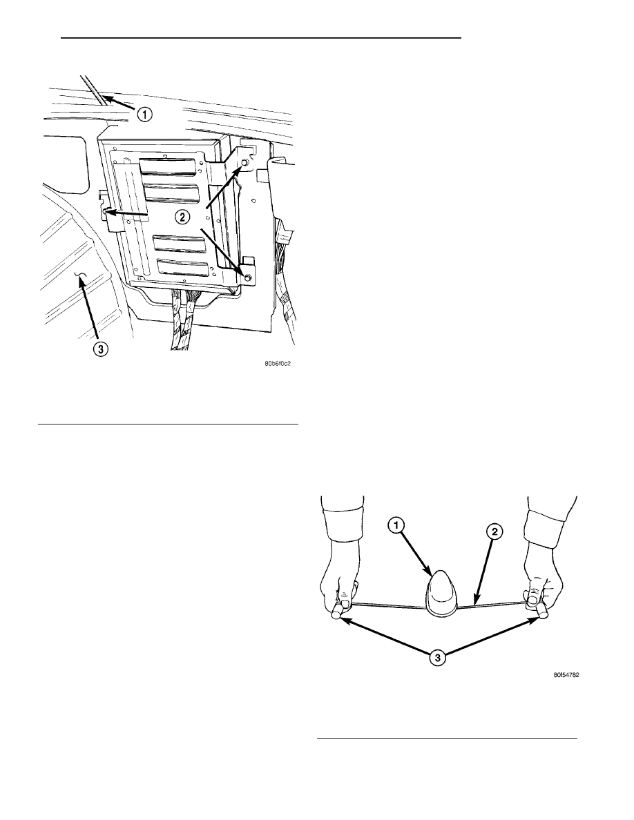
(3) A adhesive removal tool can be created by

using a 18 to 24 inch piece of nylon cord wrapped
around two handles. (Fig. 3). Using the removal tool,
guide the nylon cord under the dust seal on the for-
ward side of the antenna. Grab the handles and work
the cord through the adhesive. Continue this for 360°
around the antenna.

(4) Disconnect the wire harness connectors from

the antenna.

Fig. 2 Infinity ll Remote Amplifier Location

1 - RIGHT DECKLID SUPPORT
2 - RETAINING SCREWS
3 - RIGHT INNER FENDER WELL

Fig. 3 ANTENNA REMOVAL

1 - SATELLITE ANTENNA
2 - NYLON CORD
3 - WOODEN DOWEL ROD

LH

AUDIO/VIDEO

8A - 5

AMPLIFIER (Continued)

(5) From inside the vehicle, and using a flat

bladed tool, depress one of the retaining tabs on the
antenna. Push up the one side of the antenna con-
nector through the roof panel. Depress the other side
of the connector and remove the antenna.

(6) Remove any remaining adhesive with isopropyl

alcohol and a lint free cloth. If original antenna is
being reinstalled, remove adhesive from antenna
mounting surface.

INSTALLATION

(1) If original antenna is being installed, remove

backing from adhesive and apply to antenna base.

(2) Remove backing from the adhesive on the

antenna.

(3) Insert wire harness through hole in roof panel.

Press antenna into position until both retainers snap
into place.

(4) Connect wire harness connectors to antenna.
(5) Install headliner (Refer to 23 - BODY/INTERI-

OR/HEADLINER - INSTALLATION).

(6) Connect battery negative cable.

ANTENNA - NAVIGATION
RADIO

REMOVAL

(1) Disconnect and isolate the battery negative

cable.

(2) Remove the radio (Refer to 8 - ELECTRICAL/

AUDIO/RADIO - REMOVAL).

(3) Disconnect antenna from radio. Remove tape

securing antenna to air duct, and remove antenna.

INSTALLATION

(1) Secure antenna to air duct.
(2) Connect antenna to radio.
(3) Install radio (Refer to 8 - ELECTRICAL/AU-

DIO/RADIO - INSTALLATION).

(4) Connect battery negative cable.

ANTENNA CABLE - SATELLITE
RADIO

DESCRIPTION

The satellite radio antenna connects the roof

mounted antenna to the satellite receiver module. It
has two connectors at each end and is routed above
the headliner, then down the right side of the vehicle
floor below the carpet.

REMOVAL

(1) Disconnect and isolate the battery negative

cable.

(2) Lower the rear portion of the headliner as nec-

essary to access the underside of the satellite
antenna (Refer to 23 - BODY/INTERIOR/HEAD-
LINER - REMOVAL).

(3) Remove the lower quarter trim panel (Refer to

23 - BODY/INTERIOR/LOWER QUARTER TRIM -
REMOVAL).

(4) Remove the front and rear door sill trim (Refer

to 23 - BODY/INTERIOR/DOOR SILL TRIM -
REMOVAL).

(5) Push carpet back to access body harness.
(6) Detach the antenna cable from the body har-

ness (Fig. 4). Disconnect wire harness connectors at
each end of the cable.

INSTALLATION

(1) Secure the antenna cable to the body harness.

Connect the wire harness connectors at each end of
the antenna cable.

(2) Install the front and rear door sill trim (Refer

to 23 - BODY/INTERIOR/DOOR SILL TRIM -
INSTALLATION).

(3) Install the lower quarter trim (Refer to 23 -

BODY/INTERIOR/LOWER

QUARTER

TRIM

-

INSTALLATION).

(4) Install the headliner (Refer to 23 - BODY/IN-

TERIOR/HEADLINER - INSTALLATION).

(5) Connect the battery negative cable.

Fig. 4 ANTENNA CABLE - SATELLITE RADIO

1 - SATELLITE RECEIVER MODULE
2 - SATELLITE RADIO ANTENNA CABLE

8A - 6

AUDIO/VIDEO

LH

ANTENNA - SATELLITE RADIO (Continued)

CD CHANGER

DESCRIPTION

The 6 Disc In-Dash CD Changer (if equipped) is

located in the existing cubby bin. It is a cartridge-
less changer controlled by the radio and allows the
occupants to load up to six discs, one at a time.

OPERATION

Due to its compact design, the CD changer can

only carry out one operation at a time. For example,
you can not load a new disc while playing another at
the same time. Each operation happens sequentially.

The radio unit provides control over all features of

the CD changer with the exception of the CD load
and eject functions, which are controlled by buttons
located on the front of the CD changer. All features
you would expect, such as Disc Up/Down, Track
Up/Down, Random and Scan are controlled by the
radio, which also displays all relevant CD changer
information on the radio display.

The CD changer contains a Load/Eject button and

an indicator light for each of the six disc positions.
The individual light indicates whether a CD is cur-
rently loaded in that particular chamber of the CD
changer. Pressing the individual Load/Eject button
for a particular chamber will eject a disc currently
present in that chamber. If the chamber is currently
empty, actuating the Load/Eject button will position
that chamber to receive and load a new disc in that
chamber.

REMOVAL

(1) Open hood and disconnect the negative battery

cable remote terminal from the remote battery post.

(2) Remove ash receiver (if applicable).
(3) Using a trim stick (special tool #C-4755), gently

pry out on center trim bezel. Disconnect wiring con-
nectors to HVAC controls, cigar lighter/auxiliary
power outlet and traction control switch.

(4) Remove instrument panel center trim bezel.
(5) Remove two retaining screws to in-dash CD

changer.

(6) Pull CD changer out of instrument panel, dis-

connect wiring and remove from vehicle.

INSTALLATION

(1) Connect wiring and install CD changer into

instrument panel. Make sure the rubber bumper
engages into the instrument panel.

(2) Install two retaining screws to in-dash CD

changer.

(3) Install instrument panel center trim bezel.
(4) Connect wiring connectors to HVAC controls,

cigar lighter/auxiliary power outlet and traction con-
trol switch.

(5) Place center trim bezel into position and snap

into place.

(6) Install ash receiver (if applicable).
(7) Connect the negative battery cable remote ter-

minal to the remote battery post.

MULTIPLEXER

REMOVAL

(1) Disconnect and isolate the battery negative

cable.

(2) Remove the radio (Refer to 8 - ELECTRICAL/

AUDIO/RADIO - REMOVAL).

(3) Remove mounting fasteners (Fig. 5).

(4) Disconnect wire harness connectors and remove

multiplexer.

INSTALLATION

(1) Connect wire harness connectors and place

multiplexer into position.

(2) Install mounting fasteners.
(3) Install radio (Refer to 8 - ELECTRICAL/AU-

DIO/RADIO - INSTALLATION).

(4) Connect battery negative cable.

RADIO

DESCRIPTION

Available factory-installed radio receivers for this

model include:

• AM/FM/cassette/CD (RAZ sales code)

• AM/FM/cassette with CD changer control fea-

ture (RBB sales code)

Fig. 5 MULTIPLEXER

1 - RADIO
2 - MULTIPLEXER
3 - CD CHANGER

LH

AUDIO/VIDEO

8A - 7

• AM/FM/CD with CD changer control (RBK sales

code)

• AM/FM/cassette/CD with CD changer control

(RAD, RBT or RBY sales code) - export only

• AM/FM/DVD with GPS navigation (RB1 sales

code)

All factory-installed radio receivers can communi-

cate on the Programmable Communications Interface
(PCI) data bus network. All factory-installed receiv-
ers are stereo Electronically Tuned Radios (ETR) and
include an electronic digital clock function.

These radio receivers can only be serviced by an

authorized radio repair station. See the latest War-
ranty Policies and Procedures manual for a current
listing of authorized radio repair stations.

OPERATION

The radio receiver operates on ignition switched

battery current that is available only when the igni-
tion switch is in the On or Accessory positions. The
electronic digital clock function of the radio operates
on fused battery current supplied through the IOD
fuse, regardless of the ignition switch position.

For complete circuit diagrams, refer to the appro-

priate wiring information. The wiring information
includes wiring diagrams, proper wire and connector
repair procedures, details of wire harness routing
and retention, connector pin-out information and
location views for the various wire harness connec-
tors, splices and grounds.

REMOVAL

(1) Disconnect and isolate the battery negative

cable.

(2) Remove instrument panel center trim bezel.

(Refer to 23 - BODY/INSTRUMENT PANEL/IN-
STRUMENT PANEL CENTER BEZEL - REMOVAL).

(3) Remove four radio mounting screws.
(4) Pull radio from panel and disconnect wiring

from radio.

CAUTION: Pulling the antenna cable straight out of
the radio without pulling on the locking antenna
connector could damage the cable or radio.

(5) Disconnect the antenna cable by pulling the

locking antenna connector away from the radio (Fig.
6).

(6) Remove radio from vehicle.

INSTALLATION

(1) Place radio near instrument panel opening.
(2) Connect wiring and antenna lead to radio and

slide into place.

(3) Install four radio mounting screws.

(4) Install instrument panel center trim bezel.

(Refer to 23 - BODY/INSTRUMENT PANEL/IN-
STRUMENT PANEL CENTER BEZEL - INSTALLA-
TION).

(5) Connect the battery negative cable.

RADIO NOISE SUPPRESSION
GROUND STRAP

DESCRIPTION

Some

components

used

on

the

vehicles

are

equipped with a capacitor to suppress radio fre-
quency interference/static.

Ground straps are mounted from the engine to

each shock tower and from the body to the muffler.
The ground straps should be securely tightened to
assure good metal to metal contact.

OPERATION

Capacitors are mounted in various locations inter-

nal to the generator, instrument cluster and wind-
shield wiper motor.

Ground straps conduct very small high frequency

electrical signals to ground and require clean large
surface area contact.

Fig. 6 ANTENNA TO RADIO

1 - RADIO
2 - LOCKING ANTENNA CONNECTOR
3 - INSTRUMENT PANEL ANTENNA CABLE

8A - 8

AUDIO/VIDEO

LH

RADIO (Continued)


Content   ..  56  57  58  59   ..