Chrysler 300/300 Touring/300C, Dodge Magnum. Manual - part 2351


  Index      Chrysler     Chrysler 300/300 Touring/300C, Dodge Magnum - service repair manual


Search            


Content   ..  2349  2350  2351  2352   ..


Chrysler 300/300 Touring/300C, Dodge Magnum. Manual - part 2351


11. Install the accessory drive belt (Refer to 7 - COOLING/ACCESSORY DRIVE/BELTS-DRIVE - INSTALLATION).

12. Replace the receiver/drier if the A/C compressor is being replaced due to an internal failure (Refer to 24 -

HEATING & AIR CONDITIONING/PLUMBING/RECEIVER/DRIER - REMOVAL) and (Refer to 24 - HEATING &
AIR CONDITIONING/PLUMBING/RECEIVER/DRIER - INSTALLATION).

13. Install the air cleaner housing (Refer to 9 - ENGINE/AIR INTAKE SYSTEM/AIR CLEANER HOUSING - INSTAL-

LATION).

14. Reconnect the negative battery cable.

15. Evacuate the refrigerant system (Refer to 24 - HEATING & AIR CONDITIONING/PLUMBING - STANDARD

PROCEDURE - REFRIGERANT SYSTEM EVACUATE).

16. Charge the refrigerant system (Refer to 24 - HEATING & AIR CONDITIONING/PLUMBING - STANDARD PRO-

CEDURE - REFRIGERANT SYSTEM CHARGE).

5.7L/6.1L ENGINES

NOTE: Be certain to check the refrigerant oil level if the A/C compressor is being replaced (Refer to 24 -
HEATING & AIR CONDITIONING/PLUMBING/REFRIGERANT OIL - STANDARD PROCEDURE - REFRIGERANT
OIL LEVEL). Use only refrigerant oil of the type recommended for the A/C compressor in the vehicle.

NOTE: If an internal failure of the A/C compressor has occurred, the receiver/drier must be replaced.

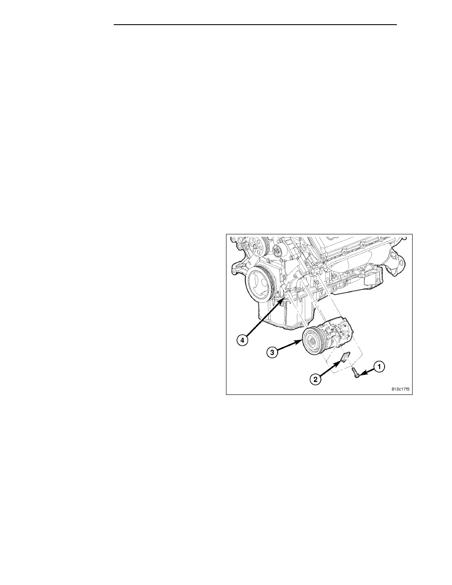
NOTE: 5.7L engine shown in illustration. 6.1L
engine similar.

1. Position the A/C compressor (3) into the engine

compartment.

2. Loosely install the three bolts (1) that secure the

A/C compressor and the automatic transmission
cooler line bracket (2) to the cylinder block (4).

3. Tighten the three bolts in the following order to 50

N·m (37 ft. lbs.):

1. Upper front bolt.

2. Lower front bolt.

3. Rear bolt.

4. Install the front end splash shields (Refer to 23 -

BODY/EXTERIOR/FRONT

END

SPLASH

SHIELDS - INSTALLATION).

5. Lower the vehicle.

24 - 438

PLUMBING

LX

6. Remove the tape or plugs from the opened fittings

on the A/C suction line (3) and the A/C discharge
line (4) and the compressor ports.

7. Lubricate new dual plane seals with clean refriger-

ant oil and install them onto the suction and the
discharge line fittings. Use only the specified seals
as they are made of a special material for the
R-134a system. Use only refrigerant oil of the type
recommended for the A/C compressor in the vehi-
cle.

8. Connect the suction and discharge lines onto the

A/C compressor (5).

9. Install the nuts (2) that secure the suction and dis-

charge lines to the A/C compressor. Tighten the
nuts to 23 N·m (17 ft. lbs.).

10. Connect the engine wire harness to the compres-

sor clutch field coil connector (1).

11. Install the accessory drive belt (Refer to 7 -

COOLING/ACCESSORY DRIVE/BELTS-DRIVE - INSTALLATION).

12. Replace the receiver/drier if the A/C compressor is being replaced due to an internal failure (Refer to 24 -

HEATING & AIR CONDITIONING/PLUMBING/RECEIVER/DRIER - REMOVAL) and (Refer to 24 - HEATING &
AIR CONDITIONING/PLUMBING/RECEIVER/DRIER - INSTALLATION).

13. Install the air cleaner housing (Refer to 9 - ENGINE/AIR INTAKE SYSTEM/AIR CLEANER HOUSING - INSTAL-

LATION).

14. Reconnect the negative battery cable.

15. Evacuate the refrigerant system (Refer to 24 - HEATING & AIR CONDITIONING/PLUMBING - STANDARD

PROCEDURE - REFRIGERANT SYSTEM EVACUATE).

16. Charge the refrigerant system (Refer to 24 - HEATING & AIR CONDITIONING/PLUMBING - STANDARD PRO-

CEDURE - REFRIGERANT SYSTEM CHARGE).

LX

PLUMBING

24 - 439

CONDENSER-A/C

DESCRIPTION

The A/C condenser (1) is located in the front of the
engine compartment behind the front fascia. The A/C
condenser is a heat exchanger that allows the high-
pressure refrigerant gas being discharged by the A/C
compressor to give up its heat to the air passing over
the condenser fins, which causes the refrigerant to
cool and change to a liquid state.

The A/C condenser is equipped with an integral auto-
matic transmission cooler (2), a tapping block (3) for
the receiver/drier (4) and mounting provisions for the
power steering cooler (5).

OPERATION

When air passes through the fins of the A/C condenser, the high-pressure refrigerant gas within the A/C condenser
gives up its heat. The refrigerant then condenses as it leaves the A/C condenser and becomes a high-pressure
liquid. The volume of air flowing over the condenser fins is critical to the proper cooling performance of the A/C
system. Therefore, it is important that there are no objects placed in front of the radiator grille openings at the front
of the vehicle or foreign material on the condenser fins that might obstruct proper air flow. Also, any factory-installed
air seals or shrouds must be properly reinstalled following radiator or A/C condenser service.

The A/C condenser cannot be repaired and, if faulty or damaged, it must be replaced.

REMOVAL

WARNING: Refer to the applicable warnings and cautions for this system before performing the following
operation (Refer to 24 - HEATING & AIR CONDITIONING/PLUMBING - WARNINGS) and (Refer to 24 - HEAT-
ING & AIR CONDITIONING/PLUMBING - CAUTIONS). Failure to follow the warnings and cautions could result
in possible personal injury or death.

1. Recover the refrigerant from the refrigerant system

(Refer to 24 - HEATING & AIR CONDITIONING/
PLUMBING

-

STANDARD

PROCEDURE

-

REFRIGERANT SYSTEM RECOVERY).

2. Disconnect and isolate the negative battery cable.

3. Remove the front fascia (Refer to 23 - BODY/EX-

TERIOR/FRONT FASCIA - REMOVAL).

4. Disconnect the automatic transmission cooler lines

(1) from the left end of the A/C condenser (5)
(Refer to 7 - COOLING/TRANSMISSION - STAN-
DARD PROCEDURE - TRANSMISSION COOLER
LINE QUICK CONNECT FITTING).

5. Install plugs in, or tape over the automatic trans-

mission cooler line fittings and the cooler ports.

6. If equipped with the 3.0L diesel engine, remove the

charge air cooler.

24 - 440

PLUMBING

LX

7. Disconnect the A/C discharge line (2) and the A/C liquid line (4) from A/C condenser (Refer to 24 - HEATING &

AIR CONDITIONING/PLUMBING/LINE-A/C LIQUID - REMOVAL) and (Refer to 24 - HEATING & AIR CONDI-
TIONING/PLUMBING/LINE-A/C DISCHARGE - REMOVAL).

8. Position the power steering fluid cooler (7) out of the way (Refer to 19 - STEERING/PUMP/FLUID COOLER -

REMOVAL).

9. Remove the receiver/drier (6) from the A/C condenser (Refer to 24 - HEATING & AIR CONDITIONING/PLUMB-

ING/RECEIVER/DRIER-A/C - REMOVAL).

10. Remove the four bolts (3) that secure A/C condenser to the radiator (8).

11. Carefully tilt the bottom of the A/C condenser forward and lower the condenser out of the vehicle.

12. If required, place the A/C condenser onto a workbench and remove the power steering cooler brackets.

INSTALLATION

NOTE: If the A/C condenser is being replaced, add 30 milliliters (1 fluid ounce) of refrigerant oil to the refrig-
erant system. Use only refrigerant oil of the type recommended for the A/C compressor in the vehicle.

1. If required, install the power steering cooler brack-

ets onto the A/C condenser.

2. Carefully position the A/C condenser (5) onto the

radiator (8).

3. Install the four bolts (3) that secure the A/C con-

denser to the radiator. Tighten the bolts to 5 N·m
(44 in. lbs.).

4. Install the receiver/drier (6) onto the A/C condenser

(Refer to 24 - HEATING & AIR CONDITIONING/
PLUMBING/RECEIVER/DRIER-A/C

-

INSTALLA-

TION).

5. Install the power steering fluid cooler (7) onto the

A/C condenser (Refer to 19 - STEERING/PUMP/
FLUID COOLER - INSTALLATION).

6. Connect the A/C discharge line (2) and the A/C liq-

uid line (4) onto the A/C condenser (Refer to 24 -
HEATING

&

AIR

CONDITIONING/PLUMBING/

LINE-A/C

DISCHARGE

-

INSTALLATION)

and

(Refer to 24 - HEATING & AIR CONDITIONING/PLUMBING/LINE-A/C LIQUID - INSTALLATION).

7. If equipped with the 3.0L diesel engine, install the charge air cooler.

8. Remove the tape or plugs from the automatic transmission cooler lines (1) and the cooler ports.

9. Connect the automatic transmission cooler lines to the cooler ports at the top of the A/C condenser (Refer to 7

- COOLING/TRANSMISSION - STANDARD PROCEDURE - TRANSMISSION COOLER LINE QUICK CONNECT
FITTING).

10. Install the front fascia (Refer to 23 - BODY/EXTERIOR/FRONT FASCIA - INSTALLATION).

11. Reconnect the negative battery cable.

12. Evacuate the refrigerant system (Refer to 24 - HEATING & AIR CONDITIONING/PLUMBING - STANDARD

PROCEDURE - REFRIGERANT SYSTEM EVACUATE).

13. Charge the refrigerant system (Refer to 24 - HEATING & AIR CONDITIONING/PLUMBING - STANDARD PRO-

CEDURE - REFRIGERANT SYSTEM CHARGE).

14. Check the automatic transmission fluid level (Refer to 21 - TRANSMISSION/TRANSAXLE/AUTOMATIC/FLUID

AND FILTER - STANDARD PROCEDURE - CHECK OIL LEVEL). Fill as required (Refer to 21 - TRANSMIS-
SION/TRANSAXLE/AUTOMATIC /FLUID AND FILTER - STANDARD PROCEDURE - TRANSMISSION FILL).

LX

PLUMBING

24 - 441


Content   ..  2349  2350  2351  2352   ..