Chrysler Le Baron, Dodge Dynasty, Plymouth Acclaim. Manual - part 210
EXHAUST EMISSION CONTROLS
INDEX
page
page
Air Aspiration System
. . . . . . . . . . . . . . . . . . . . . 24
EGR Gas Flow Test
. . . . . . . . . . . . . . . . . . . . . . 21
EGR System On-Board Diagnostics
. . . . . . . . . . . 21
EGR Tube Service—2.2L and 2.5L TBI Engines
. 22
EGR Tube Service—3.0L Engines
. . . . . . . . . . . . 22
EGR Tube Service—3.3L and 3.8L Engines
. . . . 22
EGR Valve Service—2.2L and 2.5L TBI Engines
. 22
EGR Valve Service—3.0L Engines
. . . . . . . . . . . 22
EGR Valve Service—3.3L and 3.8L Engines
. . . . 22
Exhaust Gas Recirculation (EGR) System
. . . . . . 20
Exhaust Gas Recirculation (EGR) System Test
. . 21
Heated Inlet Air System
. . . . . . . . . . . . . . . . . . . 17
Heated Oxygen Sensor (O
2
Sensor)
. . . . . . . . . . 18
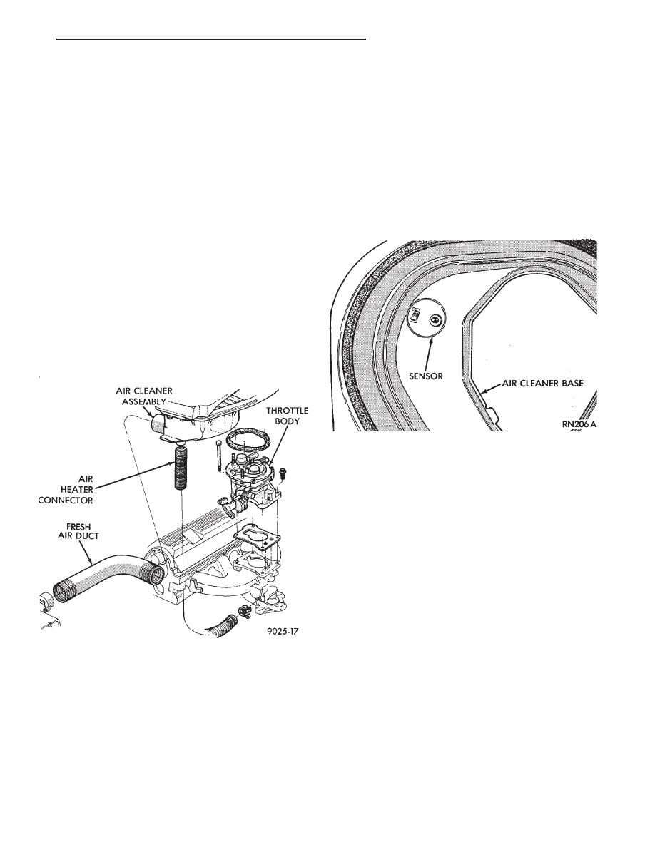
HEATED INLET AIR SYSTEM
2.5L MPI (Flexible Fuel AA-body), Turbo III, 3.0L,
3.3L and 3.8L engines do not use a heated inlet air
system.
2.2L and 2.5L TBI air cleaners have a heated air
assembly (Fig. 1). When ambient temperatures are
low, the assembly warms the air before it enters the
throttle body. The heated air assembly reduces hy-
drocarbon emissions, improves engine warm-up char-
acteristics and minimizes icing.
The heated air assembly contains a vacuum oper-
ated blend door. The blend door opens to either
heated air from a stove on the exhaust manifold or
ambient air (outside air). A vacuum diaphragm oper-
ates the door. A spring opposes the vacuum dia-
phragm. A temperature sensor controls the vacuum
diaphragm (Fig. 2). Adjustment of inlet air tempera-
ture occurs only at road load throttle positions or
when the intake manifold vacuum exceeds the vac-
uum diaphragm spring rate.
Air flows through the outside air inlet when ambi-
ent air temperature is 8°C (15°F) or more above the
air temperature sensor control temperature.
When ambient air temperature falls below the con-
trol temperature, air flows through both the ambient
and heated circuits. This occurs after the engine has
been started and the exhaust manifold starts to give
off heat. Colder ambient air cause greater air flow
through the heat stove on the exhaust manifold.
Warmer ambient air results in greater ambient air
flow through the air cleaner snorkel.
HEATED INLET AIR SYSTEM SERVICE
Heated air inlet system malfunctions may affect
driveability and vehicle exhaust emissions.
Use the following procedure to determine if the
system functions properly.
(1) Inspect the condition of the heat stove to air
cleaner flexible connector and all vacuum hoses. In-
spect them for proper attachment. Replace as neces-
sary.
(2) With a cold engine and ambient temperature
less than 46°C (115°F.), the heat control door (valve
plate) should be in the up (heat on position).
(3) With the engine warmed up and running,
check the temperature of the air entering the snorkel
or passing the sensor. When the temperature of the
Fig. 1 Heated Air Inlet System
Fig. 2 Heated Air Temperature Sensor
Ä
EMISSION CONTROL SYSTEMS
25 - 17