Chrysler Le Baron, Dodge Dynasty, Plymouth Acclaim. Manual - part 147


  Index      Chrysler     Chrysler Le Baron, Dodge Dynasty, Plymouth Acclaim - service repair manual 1993 year


Search            


Content   ..  145  146  147  148   ..


Chrysler Le Baron, Dodge Dynasty, Plymouth Acclaim. Manual - part 147


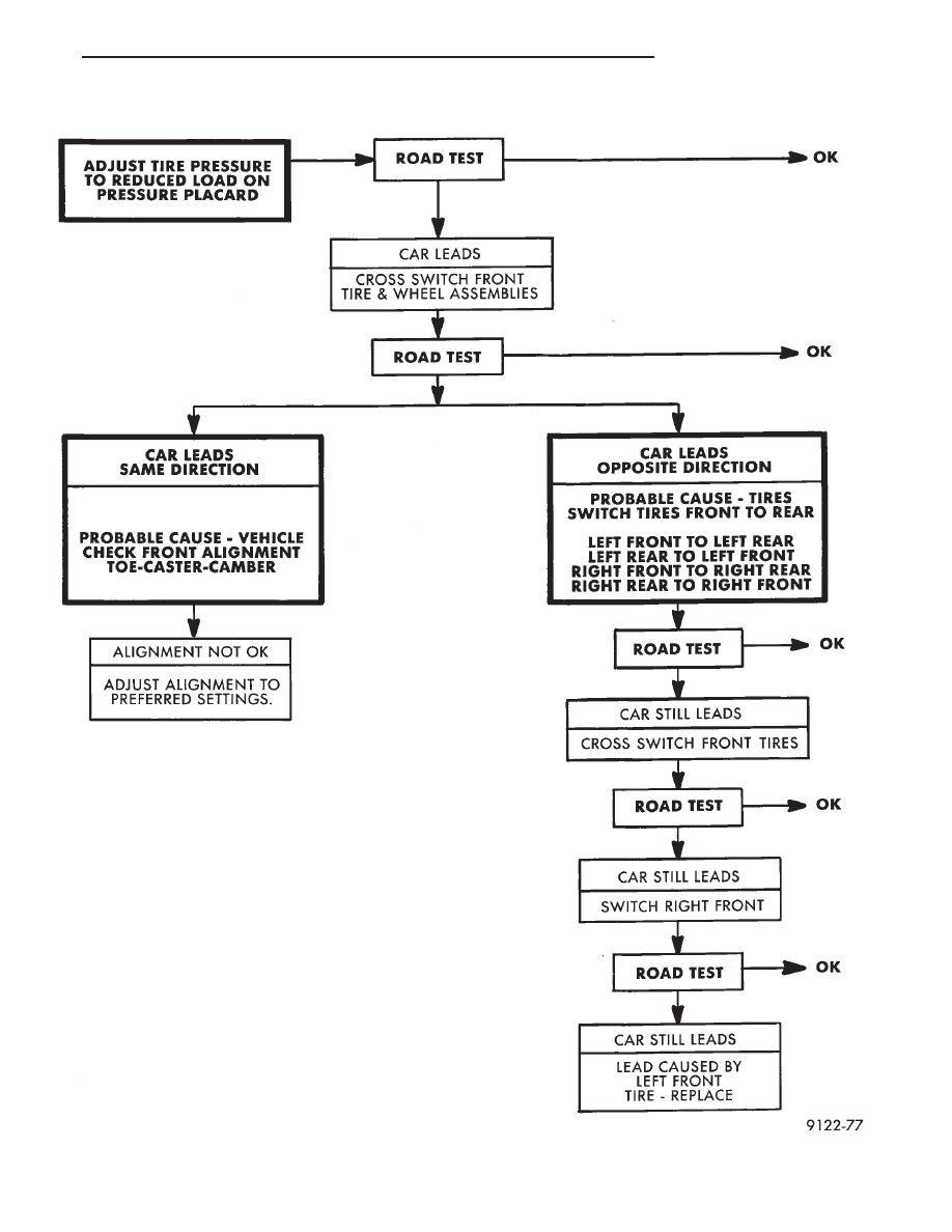
LEAD CORRECTION CHART

Ä

WHEELS—TIRES

22 - 5

WHEELS SERVICE PROCEDURES

INDEX

page

page

General Information

. . . . . . . . . . . . . . . . . . . . . . . . 6

Tire and Wheel Balance

. . . . . . . . . . . . . . . . . . . . 6

Tire and Wheel Run Out

. . . . . . . . . . . . . . . . . . . . 7

Wheel Installation

. . . . . . . . . . . . . . . . . . . . . . . . . 6

Wheel Replacement

. . . . . . . . . . . . . . . . . . . . . . . 6

GENERAL INFORMATION

Original equipment wheels are designed for proper

operation at all loads up to the maximum vehicle ca-
pacity.

All models use steel or cast aluminum drop center

wheels. The safety rim wheel (Fig. 1) has raised sec-
tions between the rim flanges and the rim well A.

Initial inflation of the tires forces the bead over

these raised sections. In case of tire failure the raised
sections help hold the tire in position on the wheel
until the vehicle can be brought to a safe stop.

Cast aluminum wheels require special balance

weights and alignment equipment.

WHEEL INSTALLATION

The wheel studs and nuts are designed for specific

applications and must be replaced with equivalent
parts. Do not use replacement parts of lessor quality
or a substitute design. All aluminum and some steel
wheels have wheel stud nuts which feature an en-
larged nose. This enlarged nose is necessary to en-
sure proper retention of the aluminum wheels.

Before installing the wheel, be sure to remove any

build up of corrosion on the wheel mounting surfaces
with scraping and wire brushing. Installing wheels
without good metal-to-metal contact could cause later
loosening of wheel nuts. This could adversely affect
the safety and handling of your vehicle.

To install the wheel, position it properly on the

mounting surface using the hub pilot as a guide. All

wheel nuts should be lightly tightened before progres-
sively tightening them in sequence (Fig. 2). Tighten
wheel nuts to 129 N

Im (95 ft. lbs.). Never use oil or

grease on studs or nuts.

WHEEL REPLACEMENT

Wheels must be replaced if they:

• have excessive run out

• are bent or dented

• leak air through welds

• have damaged bolt holes

Wheel repairs employing hammering, heating, or

welding are not allowed.

Original equipment replacement wheels are avail-

able through your dealer. When obtaining wheels from
any other source, the replacement wheels should be
equivalent in load carrying capacity. The wheel dimen-
sions (diameter, width, offset, and mounting configura-
tion) must match original equipment wheels. Failure to
use equivalent replacement wheels may adversely af-
fect the safety and handling of your vehicle. Replace-
ment with used wheels is not recommended as
their service history may have included severe
treatment or very high mileage and they could
fail without warning.

TIRE AND WHEEL BALANCE

Balancing need is indicated by vibration of seats,

floor pan, or steering wheel when driving over 90 km/h
(55 mph) on a smooth road.

Fig. 1 Safety Rim

Fig. 2 Tightening Wheel Nuts (5-Stud)

22 - 6

WHEELS—TIRES

Ä

It is recommended that a two plane dynamic bal-

ancing machine be used when a wheel and tire as-
sembly require balancing. Static balancing should be
used only when a two plane dynamic balancing is not
available.

For static imbalance, find location of heavy spot

causing imbalance and counterbalance wheel directly
opposite the heavy spot. Determine weight required
to counterbalance the area of imbalance. Place half
of this weight on the inner rim flange. Then place
the other half on the outer rim flange (Fig. 3). Off-
vehicle balancing is preferred.

TIRE AND WHEEL RUN OUT

Radial run out is the difference between the high

and low points on the tire or wheel periphery.

Lateral run out is the wobble of the tire or wheel.
Radial run out of more than 1.5 mm (.060 inch)

measured at the center line of the tread may cause
the vehicle to shake.

Lateral run out of more than 2.0 mm (.080 inch)

measured near the shoulder of the tire may cause the
vehicle to shake.

Sometimes radial run out can be reduced by relo-

cating the wheel and tire assembly on the mounting
studs (See Method 1). If this does not reduce run out
to an acceptable level, the tire can be rotated on the
wheel. (See Method 2).

METHOD 1 (RELOCATE WHEEL ON HUB)

Check accuracy of the wheel mounting surface;ad-

just wheel bearings.

Drive vehicle a short distance to eliminate tire flat

spotting from a parked position.

Make sure all wheel nuts are properly torqued

(Fig. 2).

Use run out gauge D-128-TR to determine run out

(Fig. 4).

Relocate wheel on the mounting, two studs over

from the original position.

Retighten wheel nuts (Fig. 2) until all are properly

torqued, to eliminate brake distortion.

Check radial run out. If still excessive, mark tire

sidewall, wheel, and stud at point of maximum run
out (Fig. 5), and proceed to Method #2.

METHOD 2 (RELOCATE TIRE ON WHEEL)

Rotating tire on wheel is particularly effective

when there is run out in both tire and wheel.

Remove tire from wheel and remount wheel on hub

in former position.

Check wheel radial run out (Fig. 6). It should be no

more than 0.9 mm (.035 inch).

Lateral run out (Fig. 6) should be no more than 1.1

mm (.045 inch).

If point of greatest wheel radial run out is near

original chalk mark, remount tire 180 degrees from
its original position. Recheck run out.

Fig. 3 Counterbalancing

Fig. 4 Run out Gauge D-128-TR

Fig. 5 Chalk Marking on Wheel, Tire, and Stud

Ä

WHEELS—TIRES

22 - 7

SPECIFICATIONS

Fig. 6 Checking Wheel Run out

TIRE SPECIFICATIONS

TORQUE SPECIFICATIONS

22 - 8

WHEELS—TIRES

Ä


Content   ..  145  146  147  148   ..