Chrysler Le Baron, Dodge Dynasty, Plymouth Acclaim. Manual - part 18


  Index      Chrysler     Chrysler Le Baron, Dodge Dynasty, Plymouth Acclaim - service repair manual 1993 year


Search            


Content   ..  16  17  18  19   ..


Chrysler Le Baron, Dodge Dynasty, Plymouth Acclaim. Manual - part 18


(2) Remove nuts holding bumper fascia to quarter

panels.

(3) Remove fasteners holding bumper fascia to

wheel opening flange.

(4) Disconnect license plate lamp wire connectors.
(5) Remove bolts holding bumper to rear closure

panel.

(6) Remove nuts holding bumper to energy ab-

sorber units.

(7) Separate bumper from vehicle.

INSTALLATION

Reverse the preceding operation.

AG-VEHICLE REAR BUMPER
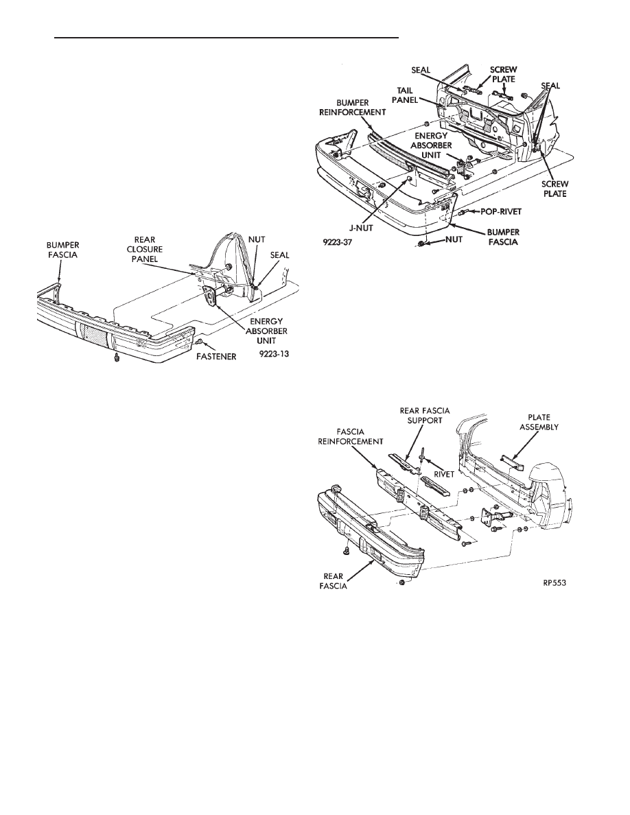
REMOVAL (FIG. 18)

(1) Raise vehicle and support on safety stands.
(2) Remove nuts holding rear fascia to luggage

compartment tail panel.

(3) Remove nuts holding fascia ends to quarter

panel end flanges.

(4) Remove pop-rivets holding bumper fascia to

wheel lip flanges.

(5) Remove nuts holding bumper fascia to quarter

panel along belt line.

(6) Support rear bumper assembly on lifting de-

vice.

(7) Remove nuts holding rear bumper reinforce-

ment to energy absorbers.

(8) Separate bumper from vehicle.

INSTALLATION

Reverse the preceding operation.

AJ-VEHICLE REAR BUMPER

REMOVAL (FIG. 19)

(1) Remove nuts holding rear fascia to quarter

panel ends.

(2) Remove push-in fasteners holding fascia to bot-

tom of bumper reinforcement.

(3) Remove nuts holding fascia to trunk tail panel.
(4) Remove bolts holding fascia to ends of bumper

reinforcement.

(5) Separate fascia from reinforcement and sepa-

rate fascia from vehicle.

(6) Support bumper reinforcement on a lifting de-

vice. Remove bolts holding reinforcement to energy
absorbers. Separate reinforcement from energy ab-
sorbers.

INSTALLATION

Reverse the preceding operation.

AP-VEHICLE REAR BUMPER

REMOVAL (FIG. 20)

(1) Raise vehicle and support on safety stands.
(2) Support rear bumper on lifting device.
(3) Remove bolts holding rear bumper reinforce-

ment to energy absorber units.

(4) Pull rear bumper assembly rearward to disen-

gage retainers from quarter panel.

(5) Separate front bumper from vehicle.

INSTALLATION

Reverse the preceding operation.

Fig. 17 Rear Bumper—AC/C-Body

Fig. 18 Rear Bumper Fascia and

Reinforcement—AG-Vehicle

Fig. 19 Rear Bumper and Fascia—AJ-Vehicle

Ä

FRAME AND BUMPERS

13 - 7

AY-VEHICLE REAR BUMPER

REAR BUMPER REMOVAL—AY/P-BODY (FIG.
21)

(1) Remove nuts holding fascia to quarter panel

ends.

(2) Support bumper assembly on suitable lifting

device and remove bolts holding bumper reinforce-
ment to energy absorber units.

(3) Separate bumper from vehicle.

INSTALLATION

Reverse the preceding operation. Align bumper

height to fit flush to bottom of tail lamp.

REAR BUMPER OVERHAUL—AY/P-BODY

(1) Position bumper assembly on a suitable padded

work surface to avoid damage to painted fascia.

(2) Remove bolts holding bumper face bar to rein-

forcement and separate face bar from assembly.

(3) Remove push-in fasteners holding fascia to re-

inforcement.

(4) Remove upper reinforcement to fascia attaching

bolts and separate reinforcement from fascia.

REAR BUMPER ASSEMBLY

Reverse the preceding operation.

REAR BUMPER REMOVAL—AY/S-BODY (FIG.
22)

(1) In luggage compartment, separate liners from

quarter panels to gain access to fascia nuts.

(2) Remove nuts holding bumper fascia to quarter

panels.

(3) Remove fasteners holding bumper fascia to

wheel opening flange.

(4) Disconnect license plate lamp wire connectors.
(5) Remove bolts holding bumper to rear closure

panel.

(6) Remove nuts holding bumper to energy ab-

sorber units.

(7) Separate bumper from vehicle.

INSTALLATION

Reverse the preceding operation.

Fig. 20 Rear Bumper—AP-Vehicle

Fig. 21 Rear Bumper—AY/P-Body

Fig. 22 Rear Bumper—AY/S-Body

13 - 8

FRAME AND BUMPERS

Ä

FRAME

INDEX

page

page

Crossmember

. . . . . . . . . . . . . . . . . . . . . . . . . . . 17

Frame Dimensions

. . . . . . . . . . . . . . . . . . . . . . . . 9

General Information

. . . . . . . . . . . . . . . . . . . . . . . . 9

GENERAL INFORMATION

In this section, references are made to Vehicle

Family (Body) codes. To determine the vehicle family
identification code, refer to the Introduction Group at
the front of this manual.

FRAME DIMENSIONS

Frame dimensions are listed in metric scale then

converted to inch scale listed in parenthesis. Engine
compartment charts include front suspension upper
strut damper mounting tower location. All dimen-
sions are from center to center of Principal Locating
Point (PLP), or from center to center of PLP and fas-
tener location.

VEHICLE PREPARATION

Position the vehicle on a level work surface. Using

screw or bottle jacks, adjust the vehicle height to the
specified PLP dimension above the Datum Line
(work surface). Vertical dimensions can be taken
from the datum line to the PLP.

ENGINE COMPARTMENT DIMENSIONS

Refer to Fig. 1, 2, 3, 4 or 5.

FRONT FRAME DIMENSIONS

Refer to Fig. 6

REAR FRAME DIMENSIONS

Refer to Fig. 7, 8, 9, 10 or 11.

Fig. 1 Engine Compartment Dimensions—AA-Body

Fig. 2 Engine Compartment Dimensions—AC-Body

Ä

FRAME AND BUMPERS

13 - 9

Fig. 5 Engine Compartment Dimensions—AP-Body

Fig. 3 Engine Compartment Dimensions—AG-Body

Fig. 4 Engine Compartment Dimensions—AJ-Body

13 - 10

FRAME AND BUMPERS

Ä


Content   ..  16  17  18  19   ..