Index Chrysler Chrysler Le Baron, Dodge Dynasty, Plymouth Acclaim - service repair manual 1993 year
Search
Content .. 3 4 5 6 ..
Chrysler Le Baron, Dodge Dynasty, Plymouth Acclaim. Manual - part 5
Ä
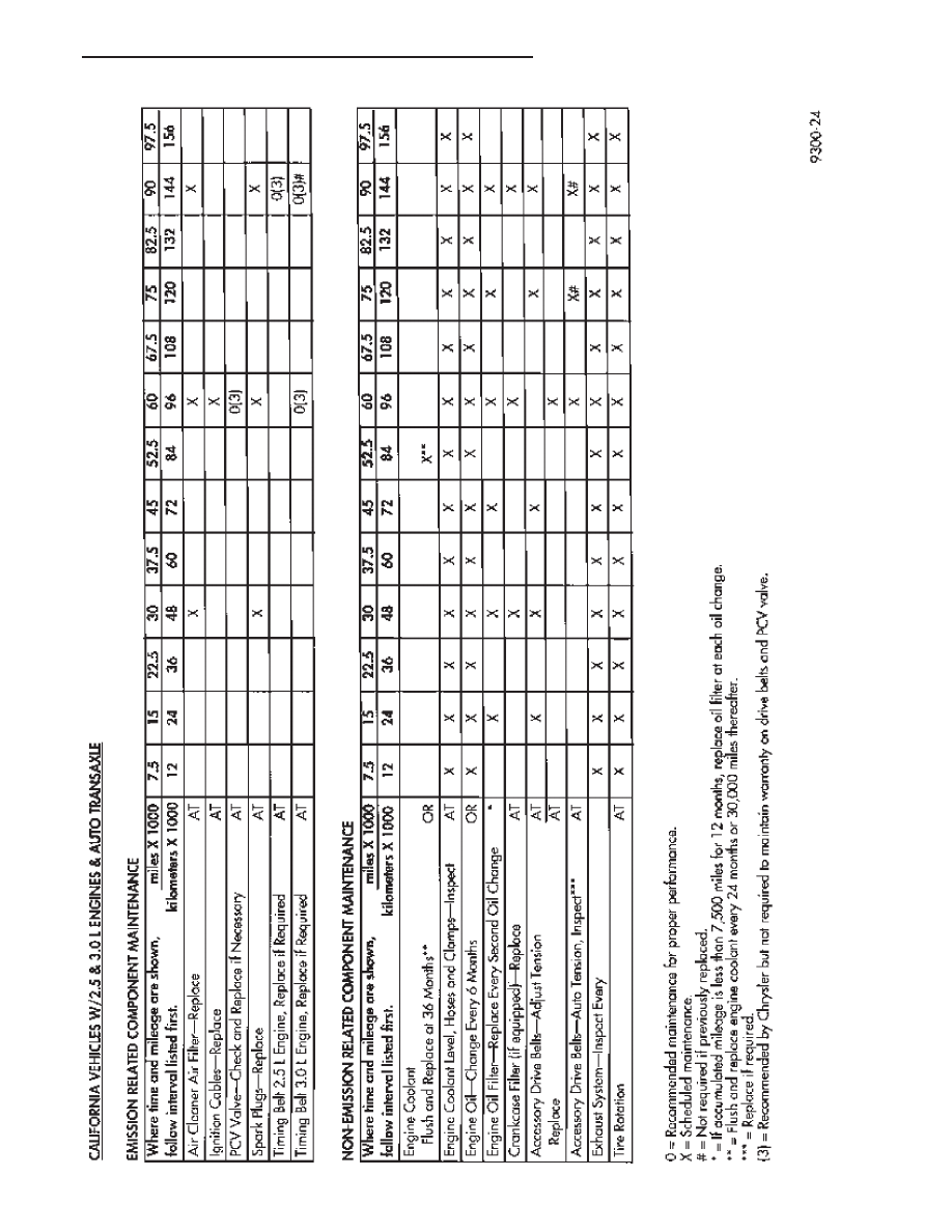
LUBRICATION AND MAINTENANCE
0 - 3