Chery Tiggo 5 (T21). Manual - part 114


  Index      Chery     Chery Tiggo 5 (T21) - service repair manual 2014 year


Search            


Content   ..  112  113  114  115   ..


Chery Tiggo 5 (T21). Manual - part 114


07–

42

07

Flywheel

Removal

1. Turn off all the electrical equipment and ignition switch.
2. Disconnect the negative battery cable.
3. Remove the transmission assembly (

See page 17-21

 for MT model, 

See page 18-130

 for CVT model).

4. Remove the clutch assembly (

See page 19-14

).

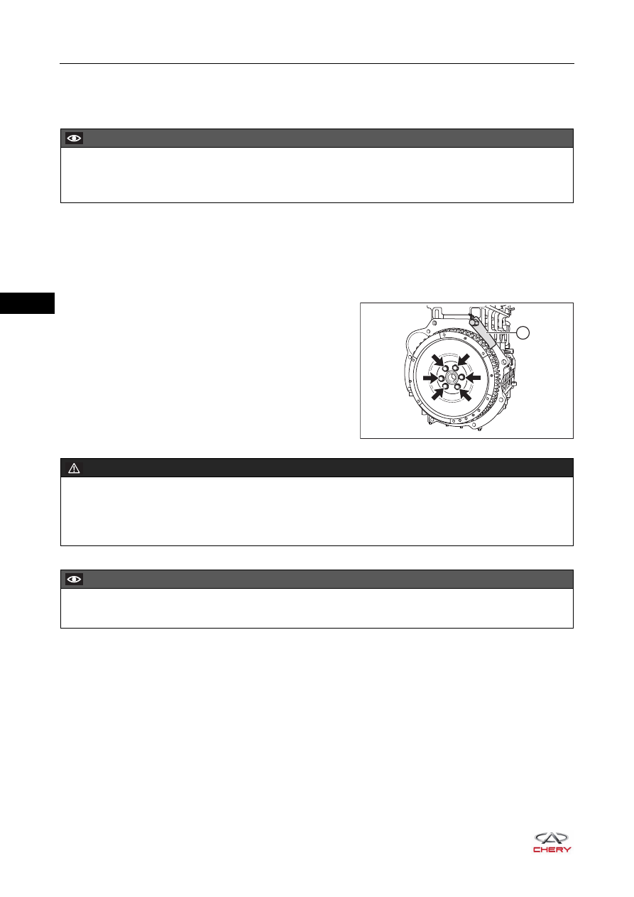
5. Remove the flywheel.

a. As shown in the illustration, install the flywheel holding 

tool (1) to hold the flywheel securely. 

b. Remove 6 fixing bolts (arrow) from flywheel, and 

remove the flywheel.

(Tightening torque: 1st step: tighten to 35 ± 5 N·m; 
2nd step: retighten by 45° ±  5°)

Inspection

1. Check if crankshaft position signal gear is distorted or deformed. If damaged, replace the flywheel. Clean 

the signal gear before installation. 

2. Check if starter drive gear ring is worn. If excessively worn, replace the flywheel.
3. Check contact surface of clutch lining. If the contact surface is damaged or excessively worn, replace the 

flywheel with a new one.

CAUTION

 Be sure to wear necessary safety equipment to prevent accidents when repairing.
 Try to prevent body paint surface from being scratched during removal and installation. 

1

RT21070290

WARNING

 Pay special attention to safety during operation, do not remove all flywheel fixing bolts without any 

auxiliary measures. 

 If necessary, other operators will be required to assist.

CAUTION

 Flywheel fixing bolts must be disposed after removal. Never reuse them.

07–

43

07

4. Measure flywheel end surface runout with the dial 

indicator. If measured value exceeds the limit, replace the 
flywheel with a new one. 
Limit for end surface runout: 0.2 mm

Installation

Installation procedures are in the reverse order of removal, and pay attention to the followings:
1. Align the flywheel installation hole with the crankshaft positioning journal and then push lightly during 

assembly. Do not tap the flywheel with a hammer. 

2. Replace the flywheel fixing bolts with precoated seal gum with new ones. 
3. Install the flywheel fixing bolts (arrow), and then hold the 

flywheel securely with the flywheel holding tool (1). 
Tighten the flywheel fixing bolts.

(Tightening torque: 1st step: tighten to 35 ± 5 N·m; 2nd 
step: retighten by 45° ± 5°)

RT21070291

WARNING

 Never reuse flywheel fixing bolts after removal. 
 Make sure to use new flywheel fixing bolts with seal gum before installation.

CAUTION

 Six bolt holes on the flywheel have asymmetrical positions. There is a matchmark hole on flywheel. The 

mark hole is located right above when 1st cylinder of engine is at the top dead center and flywheel fixing 
bolts are aligned with bolt holes of crankshaft. 

1

RT21070290

07–

44

07

Crankshaft Rear Oil Seal

Removal

1. Turn off all the electrical equipment and ignition switch.
2. Disconnect the negative battery cable.
3. Remove the transmission assembly (

See page 17-21

 for MT model, 

See page 18-130

 for CVT model).

4. Remove the clutch assembly (

See page 19-14

).

5. Remove the flywheel (

See page 07-42

).

6. Remove the crankshaft rear oil seal.

a. Using a screwdriver with the tip wrapped with tape, 

remove the crankshaft rear oil seal (1).

CAUTION

 Be sure to wear necessary safety equipment to prevent accidents when repairing.
 Try to prevent body paint surface from being scratched during removal and installation.

1

RT21070300

CAUTION

 Be careful not to damage surrounding parts and oil seal retainer when removing oil seal.
 Be careful not to damage oil pan gasket when removing rear oil seal bracket.

07–

45

07

Installation

1. Replace the new crankshaft rear oil seal.
2. Using the crankshaft rear oil seal installer (1), install the 

oil seal (2) with the part number side facing outward.

HINT:
Apply a coat of engine oil to the rear oil seal lip or 
crankshaft rear oil seal journal.

3. Other installation procedures are in the reverse order of removal.

CAUTION

 Be sure to clean the dirt around oil seal retainer and on the inner wall before installation.
 Check oil seal for damage before installation. If there is any damaged, replace it.
 Be sure to prevent the lip of crankshaft rear oil seal from being scratched during installation. 
 Be careful not to damage oil seal retainer during installation.

RT21070301

1

2


Content   ..  112  113  114  115   ..