Chery Tiggo 5 (T21). Manual - part 82
06–
170
06
DTC Confirmation Procedure
Confirm that battery voltage is over 12 V before performing the following procedures.
Turn ignition switch to LOCK.
Connect X-431 3G diagnostic tester (the latest software) to Data Link Connector (DLC).
Turn ignition switch to ON.
Use X-431 3G diagnostic tester to record and clear the DTCs stored in the ECM.
Select Read Code.
If the DTC is detected, the malfunction indicated by the DTC is current. Go to the diagnosis procedure - Step 1.
If DTC is not detected, the malfunction indicated by the DTC is intermittent (
).
Diagnosis Procedure
a. Turn ignition switch to LOCK.
b. Check ECM grounds E-026 and E-028 (
a. Disconnect ECM connector E-033.
b. Disconnect TCU connector E-030.
c. Check if connectors are normal.
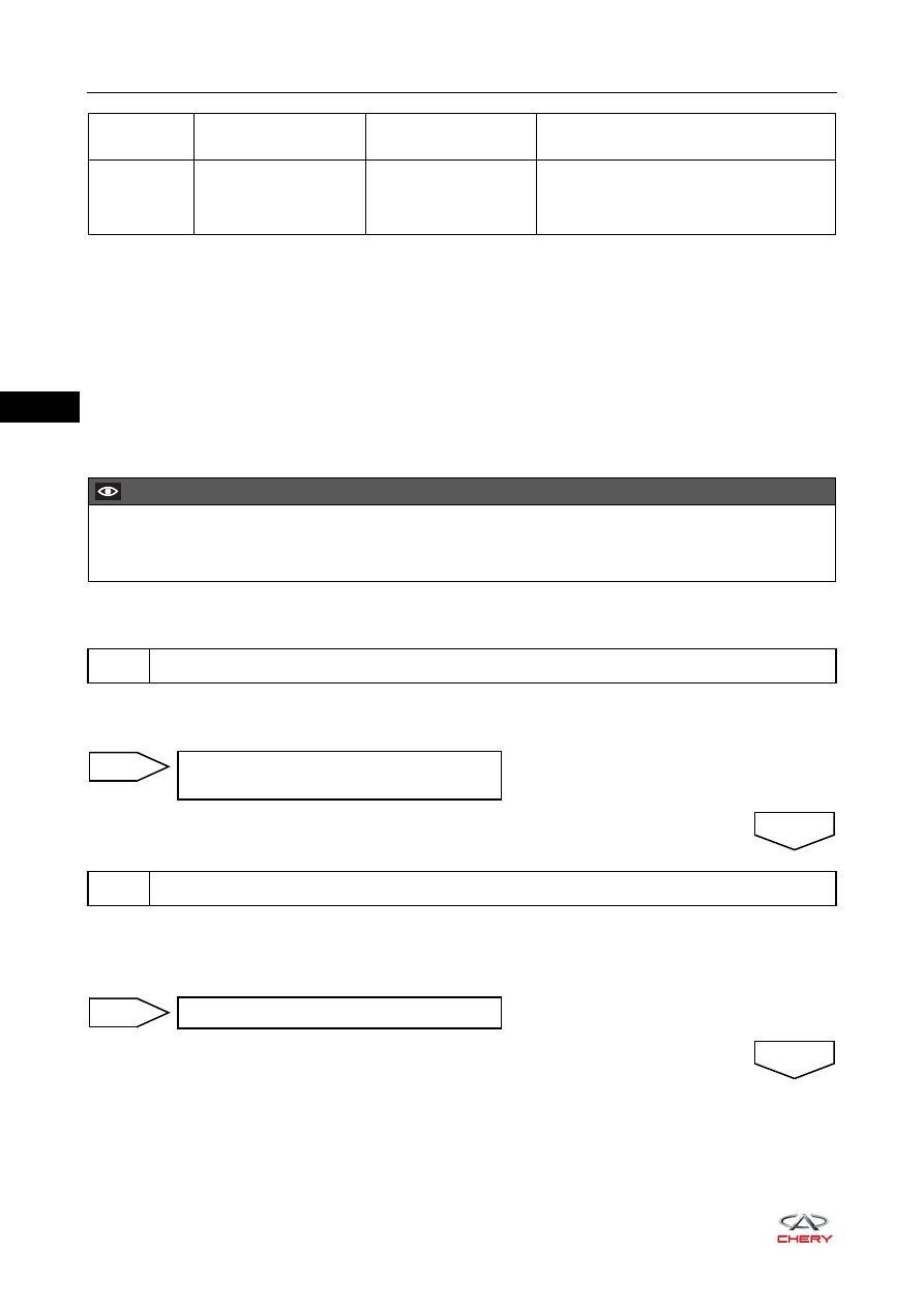
DTC Code
DTC Definition
DTC Detection
Condition
Possible Cause
U0101-87
Lost Communication
With TCM (CVT only)
Ignition switch ON
Engine running
CAN line or connector
ECM
TCM
CAUTION
When performing circuit diagnosis and test, always refer to the circuit diagram for specific circuit and
component information.
1
Check ECM ground point
Repair or replace ground wire harness or
ground point
NG
2
Check ECM connector and TCM connector
OK
Repair or replace connector
NG
OK