Chery Tiggo T11 LHD. Manual - part 50
Chery T11 Service Manual Electric Injection System
13
The fuel pump lubricating and cooling are
implemented with the help of the gasoline in
the fuel tank.
The fuel tank of this vehicle is a saddle-shaped
tank, with two fuel pump openings.
Decompression pressure: < 900 kPa
Operating voltage: 8 to 16 V
Fuel pump resistance: < 130 Ω
The injection pump in the reserve tank is used
to pump the fuel return to the main fuel tank.
Troubleshooting: The fuel pump failures are
generally
the
fuel
pressure
shortage,
non-pumping and etc. During the period of
troubleshooting, examine the fuel pressure of
the system is within the specified range, and
also examine the leakage of pipeline.
In addition, both the positive and the negative
pressure will make influence on the fuel
system.
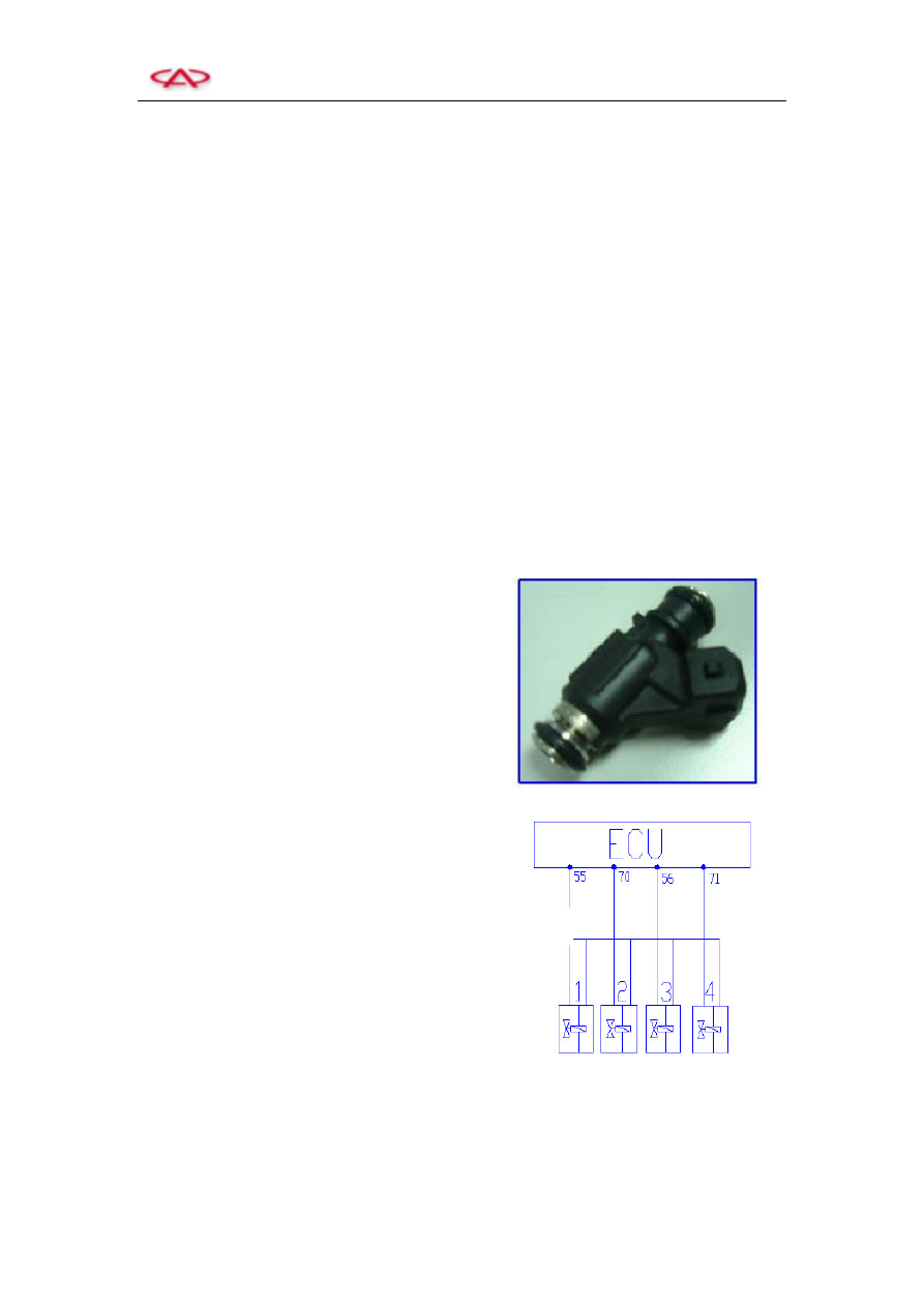
8. Electromagnetic Injector (INJ)
Application: MT 20U employs the sequential fuel
injection technology. The sequential injection
signals are provided by the intake pressure sensor
(TEMP). If the TEMP is damaged, the mode of
grouping injection is applied to control the fuel
injection in accordance with the ignition sequence.
Based on the instructions from ECU, the fuel
injector injects the fuel within the specified time,
offers engine the fuel and atomizes them.
Structure and Principle: The ECU emits the
electrical pulse to the injector coil, which forms
the magnetic field force. When the magnetic field
force rises up enough to conquer the resultant force
of the return spring pressure, gravity force of
needle valve and frictional force, the needle valve
starts to rise, and the fuel injection process begins.
When the fuel injection pulse ends, the pressure of
return spring enable the needle valve to be closed
again.
Profile of a electromagnetic injector
T11 Fuel Injector Group
Circuit diagram of electromagnetic fuel
injector
Main Relay