Chery Tiggo. Manual - part 377
Specifications
Torque Specifications
DESCRIPTION
TORQUE (N·m)
All General Service Screws
5
Recirculation door actuator screws
2
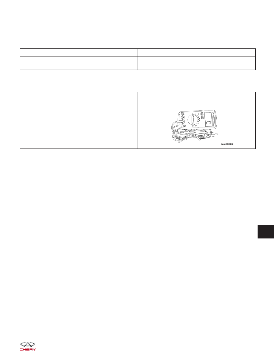
Special Tools
Digital Multimeter
Fluke 15B & 17B
GENERAL INFORMATION
13
|
|
|
Specifications Torque Specifications DESCRIPTION TORQUE (N·m) All General Service Screws 5 Recirculation door actuator screws 2 Special Tools Digital Multimeter Fluke 15B & 17B GENERAL INFORMATION 13
|