Chery Tiggo. Manual - part 266


  Index      Chery     Chery Tiggo - service repair manual 2009 year


Search            


Content   ..  264  265  266  267   ..


Chery Tiggo. Manual - part 266


5.

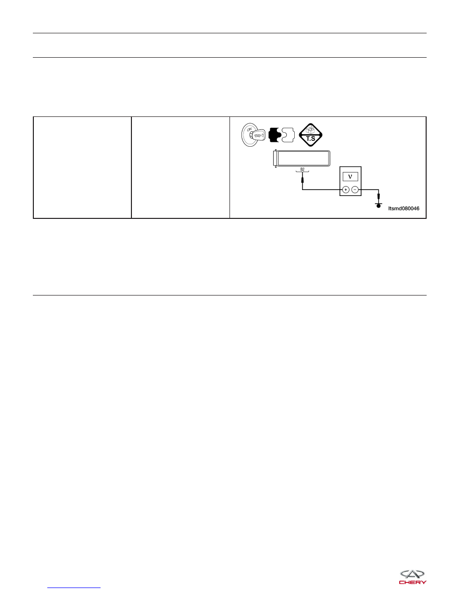
CHECK SHIFT SOLENOID VALVE 6 (SSV6) CONTROL CIRCUIT

• Turn the ignition switch off.

• Disconnect TCM connector.

• Disconnect A/T assembly connector.

• Turn the ignition switch on.

• Check harness for short to power supply.

A/T Assembly Connector

E-037 Terminal B2

Ground

Is the check result normal?

Yes

>>

Go to the next step.

No

>>

Repair or replace short to power supply in harness or connectors.

6.

CHECK DTC

• With the X-431 scan tool, read TCM DTCs.

• Refer to ⬙DTC Confirmation Procedure⬙.

Is DTC P0773 present?

Yes

>>

Replace the TCM.

No

>>

The system is now operating properly.
Reassemble the vehicle and road test to verify the customers complaint is repaired.

DIAGNOSIS & TESTING


P2709 - Shift Solenoid Valve 6 (SSV6) Open Circuit Or Short To Ground

DIAGNOSIS & TESTING

LTSMW080022T

08


On Board Diagnostic Logic
• Self-diagnosis detection logic.

DTC NO.

DTC

DEFINITION

DTC

DETECTION

CONDITION

DTC SET CONDITION

POSSIBLE

CAUSES

P2709

Shift Solenoid

Valve 6 (SSV6)

open or short to

ground circuit

Vehicle is driving

The Transaxle Control Module

(TCM) will set this DTC when the
TCM detected an improper voltage
drop when it tries to operate the
solenoid valve.

• Shift Solenoid
Valve 6 (SSV6)

• Harness or
connectors (The
sensor circuit is
open or shorted)

• Transaxle
Control Module
(TCM)

DTC Confirmation Procedure:

Before performing the following procedure, confirm that battery voltage is more than 12 V.

• Connect the X-431 scan tool to the Data Link Connector (DLC) - use the most current software available.

• After connection, press [POWER] key to start X-431.

• Turn ignition switch on, with the scan tool, view and erase stored DTCs in the TCM.

• Start the engine and warm it to normal operating temperature.

• Drive the vehicle in 1st, 2nd, 3rd and 4th gears.

• With the scan tool, select view DTC and data stream.

• If the DTC is detected, the DTC condition is current. Go to Diagnostic Procedure - Step 1.

• If the DTC is not detected, the DTC condition is intermittent (See Diagnostic Help and Intermittent DTC Trou-

bleshooting in Section 08 Transaxle & Transfer Case for more information).

• If using the appropriate diagnostic test tool, you can diagnose the TCM harness while the TCM is still con-

nected.

• Using the appropriate diagnostic test tool in this way will help prevent electrical connector terminal damage.

NOTE :
While performing electrical diagnosis & testing, always refer to the electrical schematics for specific circuit
and component information.

DIAGNOSIS & TESTING


Diagnostic Procedure

1.

CHECK A/T SOLENOID SIGNAL

• With the scan tool, select view DTC and data stream for A/T.

• Start the engine.

• Monitor the value of the gear position as indicated in the following table while driving:

X-431 REFERENCE VALUE

SELECT

POSITION

RANGE

SHIFT

SOLENOID

VALVE 1

SHIFT

SOLENOID

VALVE 2

SHIFT

SOLENOID

VALVE 3

SHIFT

SOLENOID

VALVE 4

P

0

-

-

#

-

R

R

-

-

-

-

N

0

-

-

#

-

D

1

-

-

#

#

2

-

#

-

#

3

-

-

-

-

4

#

#

-

-

Is the check result normal?

Yes

>>

The condition that caused this DTC is intermittent (See Diagnostic Help in Section 08 Transaxle &

Transfer Case).

No

>>

Go to the next step.

2.

ACTUATE TEST

• With X-431, perform the solenoid actuate test.

• The solenoid should be heard.

Is the check result normal?

Yes

>>

Go to step 6.

No

>>

Go to the next step.

DIAGNOSIS & TESTING

08


Content   ..  264  265  266  267   ..