Chery Tiggo. Manual - part 136
Check reference values between ECM terminals and ground under the following conditions:
ECM TERMINAL NO.
ITEM
CONDITION
DATA (DC VOLTAGE)
3
ECM ground (IGN)
Ignition switch: ON
Approximately 0 V
51
ECM ground (Signal)
Ignition switch: ON
Approximately 0 V
53
ECM ground (Signal)
Ignition switch: ON
Approximately 0 V
61
ECM ground (Power)
Ignition switch: ON
Approximately 0 V
80
ECM ground (Power)
Ignition switch: ON
Approximately 0 V
Confirmation Procedure:
Before performing the following procedure, confirm that battery voltage is more than 12 V.
• Turn ignition switch off.
• Connect the X-431 scan tool to the Data Link Connector (DLC) - use the most current software available.
• Turn ignition switch on.
• Start engine then select view data stream.
• If the data stream is detected, the condition is intermittent (See Diagnosis & Testing Diagnostic Help in Section
03 Electronic Engine Controls).
• If data stream is not detected, go to Diagnostic Procedure - Step 1.
1.
INSPECTION START
• Start engine.
Is engine running?
Yes
>>
Go to step 7.
No
>>
Go to step 2.
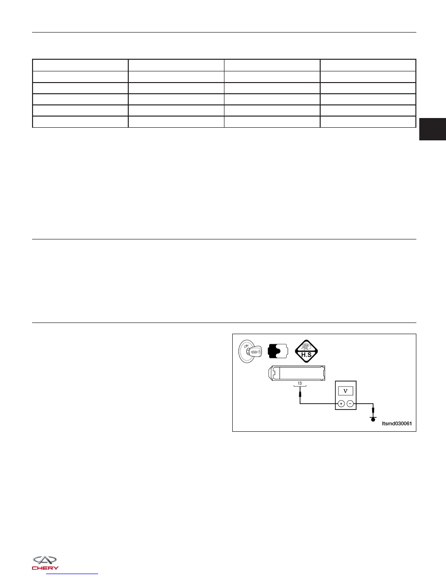
2.
CHECK ECM POWER SUPPLY CIRCUIT - (1)
• Turn ignition switch off and then on.
• Check voltage between ECM terminal 13 and
ground.
• Battery voltage should exist.
Is the check result normal?
Yes
>>
Go to step 4.
No
>>
Go to step 3.
DIAGNOSIS & TESTING
LTSMD030061
03