Chery Tiggo. Manual - part 103


  Index      Chery     Chery Tiggo - service repair manual 2009 year


Search            


Content   ..  101  102  103  104   ..


Chery Tiggo. Manual - part 103


6.

CHECK MAF SENSOR

• For 1.8L engine, check air flow in data stream.

ECM TERMINAL NO.

ITEM

CONDITION

DATA (AVERAGE DC

VOLTAGE)

37

Sensor signal

• Engine is running

• ECT: 78°C

• Idle: 795 RPM

• IAT: 36°C

• IAT signal voltage:
1.88 V

Approximately 322 kg/h

Approximately 1.39 V

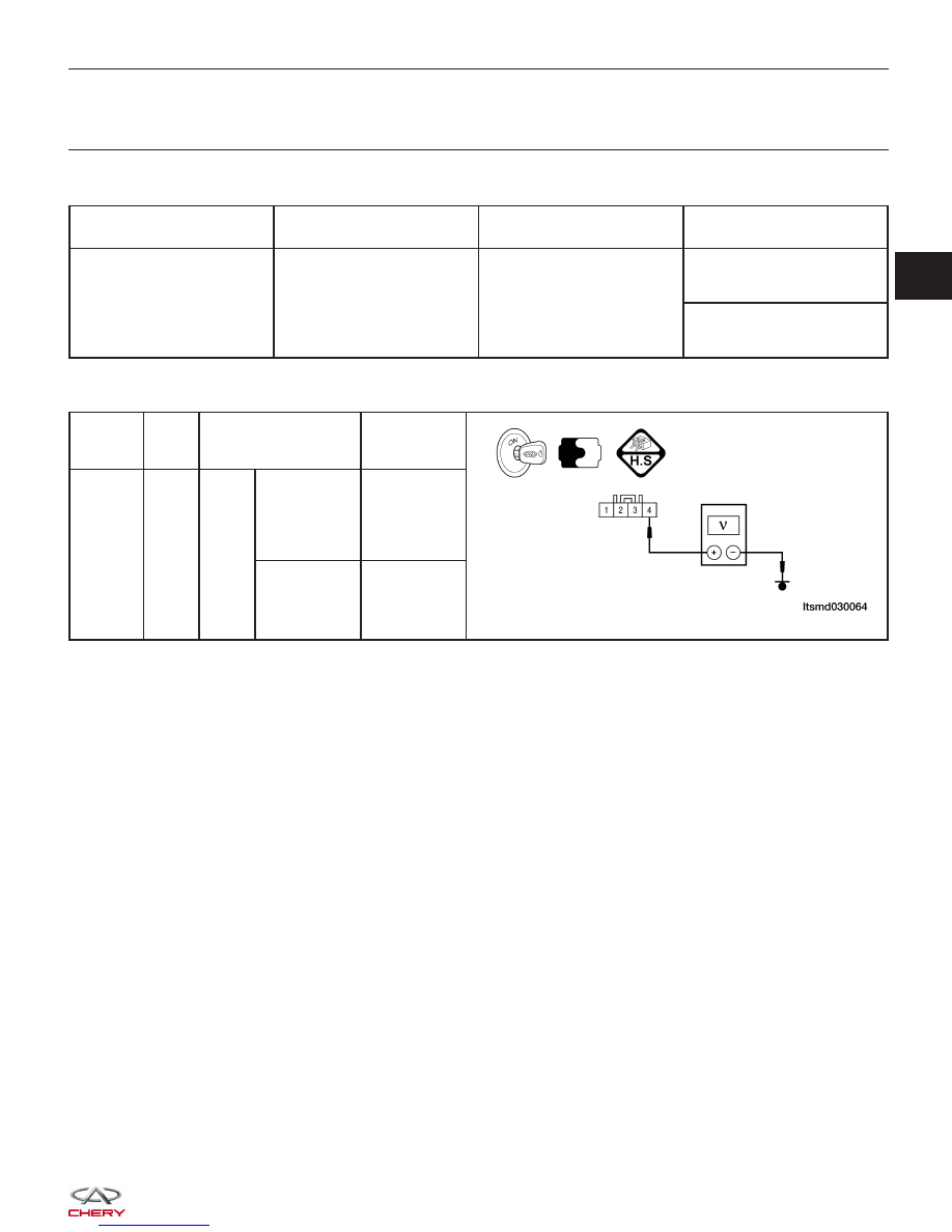
• For 1.6L engine, check MAP sensor signal voltage.

TERMINAL

NO.

ITEM

CONDITION

DATA (DC

VOLTAGE)

4

MAP

sensor

Engine:

Running

• Engine
running: Idle

• Press

accelerator
pedal slowly

Approximately

1.3 V

• Press
accelerator
pedal quickly

Up to

Approximately

4 V

(instantaneous)

Is the check result normal?

Yes

>>

Go to the next step.

No

>>

Check connectors for rusted terminals or loose connectors in the air flow sensor circuit or ground.

DIAGNOSIS & TESTING

03


7.

CHECK THE FUEL PRESSURE

• Release fuel pressure to zero.
• Install fuel pressure gauge (2) and check fuel

pressure.

• Observe the following fuel pressures when testing (See Fuel Pressure Test in Section 04 Fuel Delivery).

FUEL PRESSURES

Key On

400 kPa (4.0 bar)

Key Off

380 kPa (3.8 bar) in 10 minutes

Engine: Idle

400 - 420 kPa (4.0 - 4.2 bar)

Is the check result normal?

Yes

>>

Go to step 9.

No

>>

Go to the next step.

8.

DETECT MALFUNCTIONING PART

• Check the following:

− Fuel pump and circuit
− Fuel pressure regulator
− Fuel lines
− Fuel filter for clogging

Is the check result normal?

Yes

>>

If with the X-431, go to the next step.
If without the X-431, go to step 10.

No

>>

Repair or replace malfunctioning part.

DIAGNOSIS & TESTING

BESM030020


9.

PERFORM ACTIVE TEST FUNCTION

• Start engine.

• Select ⬙ACTIVE TEST⬙ menu.

• Perform injector active test.

• Make sure that each test produces a momentary engine speed drop.

Is the check result normal?

Yes

>>

Go to step 12.

No

>>

Go to the next step.

10.

CHECK FUNCTION OF INJECTOR

• Listen to each injector operating sound.

• Operating sound should exist.

Is the check result normal?

Yes

>>

Go to step 12.

No

>>

Go to the next step.

DIAGNOSIS & TESTING

03


11.

CHECK INJECTOR POWER SUPPLY CIRCUIT AND CONTROL CIRCUIT

• Turn ignition switch off.

• Disconnect injector harness connector (1).

• Turn ignition switch on.

• Check injector supply voltage between sensor ter-

minal and ground in the electrical connector.

• Battery voltage should exist.

• Turn ignition switch off.

• Disconnect ECM harness connector.

• Check harness continuity between following terminals.

INJECTOR NO.

ECM

TERMINAL

INJECTOR

TERMINAL

1

27

2

2

6

2

3

7

2

4

47

2

• Continuity should exist.

• Check harness for short to power.

Is the check result normal?

Yes

>>

Go to step next step.

No

>>

Repair or replace circuit for an open or short to power or short to ground in harness or connectors.

DIAGNOSIS & TESTING

BESM040006

LTSMD030024


Content   ..  101  102  103  104   ..