Chery Tiggo. Manual - part 66
CONNECTING ROD AXIAL CLEARANCE
DESCRIPTION
SPECIFICATION
LIMIT
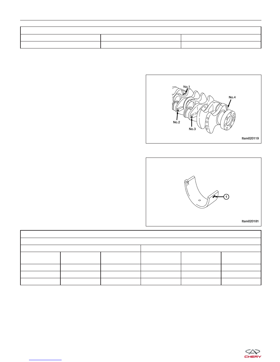
Connecting Rods
0.10 - 0.25 mm
0.4 mm
Connecting Rod Bearings
• Perform the following steps when replacing the connecting rod bearings:
− Measure and record the External Diameter of
the connecting rod journals.
− Use the connecting rod bearing identification
table to locate the desired bearing.
• The bearing will have an identification mark (1) imprinted in the position as shown.
IDENTIFYING CONNECTING ROD BEARINGS
Internal Diameter of Connecting Rods (without bearing): 48.000 - 48.015 mm
Crank Journal
Connecting Rod Bearing
Group
Identification
Color
External
Diameter (mm)
Identification
Number
Identification
Color
Thickness (mm)
1
Yellow
44.995 - 45.000
1
Yellow
1.487 - 1.491
2
None
44.985 - 44.995
2
None
1.491 - 1.495
3
White
44.980 - 44.985
3
Blue
1.495 - 1.499
NOTE :
As an example, if the measurement of the external diameter of the connecting rod journal is 44.996 mm, it will be
identified as Group 1 in the table. If the crankshaft has been replaced, check the identification color applied to the
new crankshaft journal. If the journal is yellow, the crankshaft bearing will be from Group 1, and the connecting rod
bearing will be identified as 1.
ENGINE UNIT REPAIR
LTSM020119
LTSM020181