Chery QQ6 (S21) / S12LHD. Manual - part 144


  Index      Chery     Chery QQ6 (S21) / S12LHD - service repair manual


Search            


Content   ..  142  143  144  145   ..


Chery QQ6 (S21) / S12LHD. Manual - part 144


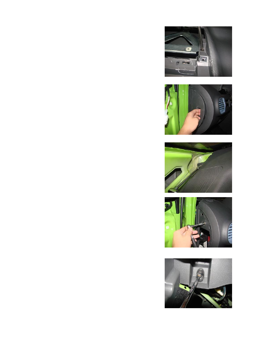
1.23. Use a cross  head screwdriver  to  loosen  off  the two screws  on 
the console.   


1.24.  Pull  off  the  central  switch  box  shield  to  the  left  Instrument 
Panel.   


1.25. Use a 8# wrench to  disassemble the bolts to  the left and right 
of the Instrument Panel (with 3 bolts for the top/middle/bottom part 
respectively, i.e. 9 in total).   


1.26.  Use  a  8#  sleeve  wrench  to  loosen  off  the  four  bolts  that 
connect  the  console  and  the  instrument  beam  and  another  bolt 
behind the instrument panel.   


1.27. Unplug the harness plugs of the left and right loudspeakers.   


1.28. Take out the Instrument Panel.   


Notes:  1.  Disconnect  the  battery  negative  before  disassembling  the 

electrical equipment.   

2.  Don’t  wait  until  all  the  Instrument  Panel  bolts  are 

disassembled before you disassemble the ones on the other 
side, or the Instrument Panel are likely to get deformed.   


2. Installation Steps 

2.1. The installation steps are reverse to those for removal. 


2.2. Notes 

.  Double

-wind  channels  should  agree  with  the  air-conditioner 

outlet connector and be installed properly  without any  air leak, and 
the  Instrument  Panel  air  channel  should  not  conflict  with  the 
Instrument  Panel  crossbeam,  the  evaporator  and  other  parts,  or  the 
Instrument Panel and its accessories will not be installed properly.   

.  The 

Instrument  Panel  should  not  interfer  with  the  front 

windscreen  or  affect  its  installation  and  an  even  clearance  should 
exist between the Instrument Panel and the windscreen.   

. The clearances between the 

Instrument Panel and either sides  of 

the vehicle body should be consistant and meet the requirements for 
assembling the door weather strips.   

3. Methods for Clearing Instrument Maintenance Indicator 

1. Clearing with diagnosis equipment:   

.  Using  the  X431  diagnosis  equipment:  Select  the  OBD

-


diagnosis  connector  and  connect  it  with  the  diagnosis  interface 
below the instrument panel; turn  on the ignition switch and start the 
diagnosis  equipment;  choose  the  latest  edition  and  select  the 
instrument  panel  system;  select  "ATECH  Instrument  System",  and 
then 

"Action 

Testing"; 

select 

"Maintenance 

and 

service 

requirements",  and  then  click  “confirm”  to  clear  the  instrument 
maintenance indicator, and then exit the diagnosis equipment; 

.  U

sing  K81/K61  diagnosis  equipment:  Select  the  MITSUBISHI 

diagnosis  connector  and  connect  it  with  the  diagnosis  interface 
below the instrument panel; turn  on the ignition switch and start the 
diagnosis  equipment;  choose  the  latest  edition  and  select  the 
instrument panel system; select "Instrument System (ATECH)", and 
then  "Action  Testing";  select  "To  clear  maintenance  requirement 
indicator",  and  then  press  “enter”  to  clear  the  instrument 
maintenance indicator, and then exit the diagnosis equipment; 
2. Clearing by the adjusting knob as follows:   

.  Insert  the  key  into  the  ignition  switch  and  get  it  to  the  position 


“ ”

Ⅰ ; 

. Press the mode adjusting knob by hand and let it stay there when 


you turn the key to “

” position

. Push down the mode adjusting knob and  k

eep  it there  for about 

20  seconds  before  you  release  the  knob,  and  then  the  maintenance 
indicator will be cleared.   

II. Removal of Instrument Panel crossbeam 

1. Removal Steps 

1.1.  Disassemble  the  Instrument  Panel  assembly  (See  Removal  of 
Instrument Panel) 
1.2.  Use  a  13#  sleeve,  combined  wrench  to  loosen  off  the  two  nuts 
and four bolts that connect the Instrument Panel crossbeam with the 
left/right A-pillars.   


Content   ..  142  143  144  145   ..