Chery QQ6 (S21) / S12LHD. Manual - part 70


  Index      Chery     Chery QQ6 (S21) / S12LHD - service repair manual


Search            


Content   ..  68  69  70  71   ..


Chery QQ6 (S21) / S12LHD. Manual - part 70


with brake master cylinder.   


18.2. Disc brake   

18.2.1. Thickness of brake disc 

The  standard  thickness  of  front  brake  disc  (ventilation  disc)  shall  be  17  mm  with  the 

serviceability limit of 15 mm; and if above the limit, the front brake disc shall be replaced. 


18.2.2. Thickness of brake lining 

The standard thickness of front brake lining shall be 10 mm, with the serviceability limit of 3 

mm,  and  the  remaining  thickness  while  the  brake  lining  thickness  limit  shall  not  be  less  than 

3mm. 

The standard thickness of rear brake lining shall be 5 mm, with the serviceability limit of 1 mm, 

and the remaining thickness while the brake lining thickness limit shall not be less than 1 mm. 


18.3. Brake disc runout check 

Check the brake disc face runout with a dial gauge. The serviceability of front brake disc shall be 

0.03 mm. If above the limit, replace it.   

IMPORTANT NOTICE: 

After the completion of replacement of friction lining or brake disc, step on the brake several times 

to enable the brake lining to run-in with the brake disc. Caution the safety! 

After  the  replacement  of  brake  lining,  check  whether  the  brake  fluid  level  is  between  MIN  and 

MAX marks. 


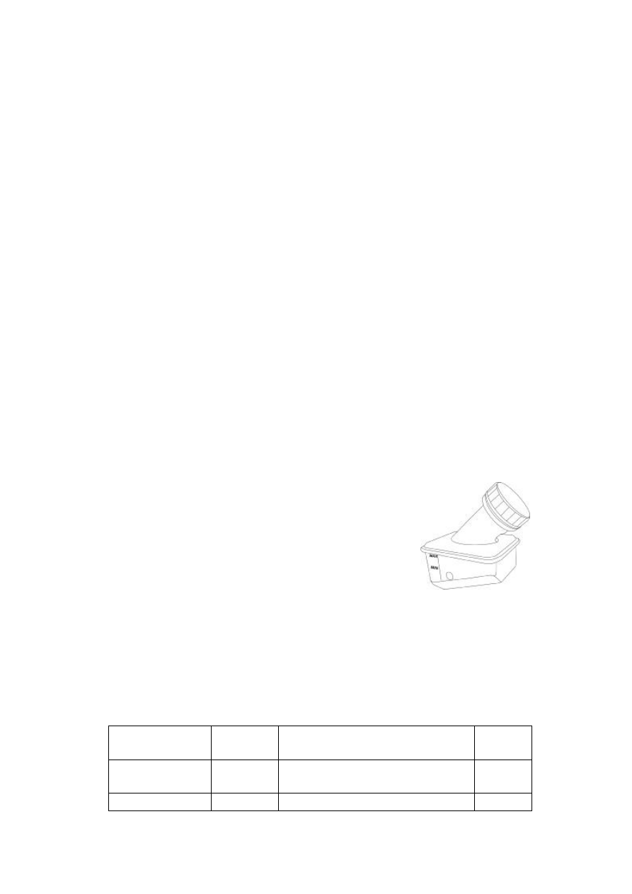
18.4. Brake fluid check and replacement   

The brake fluid reservoir is located at the right rear portion of engine 

compartment.  The  fluid  level  must  be  between  the  MIN  and  MAX 

marks at the side of the fluid reservoir. If the fluid level falls down to 

the  MIN  mark,  the  brake  fluid  level  warning  light  will  light.  In  this 

case,  please  refill  the  brake  fluid  conforming  to  the  CHERY’s 

specification, and check the leakage of this system. 

In case that the brake fluid is refilled, make certain that it is absolutely 

clean. 

19. Check and Maintenance of Vehicle Bottom 

19.1. Bolt torque check   

Check the torque of chassis bolts one-by-one with a torque wrench. The reference torques 

are as shown in the table below:   

Part Description


QTY    per 

singlel vehicle


Remark


Torque 

(Nm)


Bolt


2


Used to secure the steering wheel and 

subframe (right)


100±10


Bolt


2


Used to secure the steering wheel and 

100±10


subframe (left)


Nut


2


Used to secure the tie rod and steering 

knuckle


35±3


Bolt


2


Lower swing arm and subframe connecting 

rod (left, right)


100±10


Flange face metal 

retaining nut 


2


Lower swing arm and subframe connecting 

rod (left, right)


100±10


Bolt


2


Subframe and body (front)


150±10


Bolt


2


Subframe and body (rear)


150±10


Bolt


1


Lateral suport bar and body 


100±10


Nut


1


Lateral suport bar and body 


100±10


Bolt


1


Lateral suport bar and rear shaft


100±10


Bolt


2


Rear trailing arm    and body 


100±10


Bolt


4


Rear trailing arm hinge and rear shaft


60±5 

Nut


4


Rear trailing arm hinge and rear shaft


60±5 

Flange face metal 

retaining nut 


4


Sliding column and steering knuckle


100±10


Bolt


4


Sliding column and steering knuckle


100±10


Nut


4


Stabilizer bar and lower swing


60±5 

Bolt


4


Installed to the subframe 


25±5 

Flange face metal 

retaining nut 


2


Push bar and subframe 


100±10


Flange face metal 

retaining nut 


4


Push bar and lower swing


60±5 

Flange face metal 

retaining nut 


4


Push bar and lower swing


100±10


Nut


2


Used to connect the rear shock absorber 

and body 


100±10


Bolt


2


Used to connect the rear shock absorber 

and rear shaft


100±10


Wheel nut


16


Used to secure the tire and brake   

110±10


Self-locking nut


Used to secure the drive shaft and tire (front) 

270±10 

Lock nut 

brake drum and rear shaft 

250±10 


19.2. Rubber parts check   

Check the ageing or damage of the rubber parts at the bottom of vehicle. If aged or damaged, 

replace it in time.


19.3. Ball pin check   

Check the crack and other possible defects of ball pin. If any abnormal symptom is found, replace 

it in time. 

20. Check and Maintenance of Intake and Exhaust Systems 

Check the cleanness of air cleaner element, and replace it as required;   

Check the leakage and clogging of intake and exhaust systems;   

Check the damage of precatalytic converter assy, three-way catalytic converter assy, front muffler 

assy, and rear muffler assy. If damaged, replace it. 

21. Check and Maintenance of Fuel System 

Check the ageing, breakage and leakage of fuel pipes. If the symptom(s) occur, please replace the 

related pipe;   

Check the fuel pressure of fuel system. 


22. Check and Maintenance of Steering System 

Check the torque of bolts of steering system. The reference torques are shown in the table 

below:   

Part Description 

QTY    per 

singlel vehicle


Remark


Torque 

(Nm)


Bolt


1


Used to secure the steering wheelinput 

shaft and universal joint 


25±5


Steering wheel 

installation nut


1


Steering wheel fixing nut


35±3


Nut


4


Used to secure the steering column and IP 

cross beam


25±5


Bolt


3


Used to secure the universal joint 

protective sleeve and front side


9±3


Bolt


2


Used to secure the steering wheel and 

subframe (right)


100±10


Bolt


2


Used to secure the steering wheel and 

subframe (left)


100±10


Nut


2


Used to secure the tie rod and steering 

knuckle


35±3


Bolt


2


Used to secure the single pipe clamp to the 

suspension support, and secure the 

high-pressure pipe to the vehicle body


9±3


Check the leakage of power steering pump and its pipes; and check the power steering oil level. 

23. Check and Maintenance of A/C System 

In case of the maintenance of the vehicle A/C system, the following procedures shall be conducted: 

first, listen; second, look; third, touch; and fourth, check. Its specific content is:   

First, listen: 

Determine the  operating  condition  of compressor according to the sound from the  compressor. For 

the normal operating, only the even valve plate motion sound from the compressor can be heard. If 

the slap sound can be heard, it is generally the fluid slugging sound or hammering of the coolant. If 

a  serious  friction  sound  is  emitted  from  the  machine  body  and  the  clutch  sometimes  gives  out  the 

friction  sound  and  is  heated,  it  is  caused  due  to  the  excessive  load  of  compressor,  shortage  of 

lubrication oil or oil-break, and the slippage of the clutc. If there is a slap sound in the exterior of the 

vehicle, it is caused due to either the belt loose, or the serious wear.   

If the continuous impact sounds of the motion parts in the machine body can be clearly heard during 

the  shutdown  of  the  machine,  it  is  caused  due  to  the  serious  wear  of  interior  motion  parts,  which 

results  that  the  clearance  between  the  shaft  and  bearing,  piston  and  cylinder  body,  and  connecting 

rod and shaft is large or loose.   

Second, look: 

Check  the  cleanness  of  surface  of  the  condenser  first,  avoid  that  the  foreign  materials  and  mud 

acttach to the condenser,  which  may  make an influence  on the  cooling effect.  In  general, regularly 

rinse the condenser with water. CAUTION: When the condenser is rinsing, DO NOT touch the fins 

to deform them. For the deformed fins, carefully correct them with a long nosed pliers.   

At  the  air  inlet  of  vehicle  air  conditioner’s  evaporator,  some  air  filters  are  generally  installed. 

Regularly check the evaporator every week, clear the foreign materials, and clean the mud from the 

evaporator  surface  with  the  high-pressed  air  so  as  to  avoid  that  the  heat  transfer  coefficient  falls 

down and the A/C air is contaminated. The contents checked regularly are: 
Ø  Check whether there are some oil stains in all connecting sections of the A/C cooling system. If 

there are some oil stains, it indicates that the leakage may occurs here. Immediately remove the 

trouble A.S.A.P. For the cooling sytem, the leakage position(s) must be mainly inspected. The 

mainly-inpsected  positions  also  include:  compressor  shaft  seal,  front  and  rear  cover  plate 

gasket, safety valve and etc. 

Ø  Check  the  wear,  ageing,  blister,  crack  and  leaky  oil  stains  of  all  hoses.  Since  the  vehicle’s 

cooling  and  heating  systems  adopt  a  lot  of  rubber  hoses,  these  hoses  may  be  worn  due  to 

contact with the vehicle body during the vehicle is traveling and vibrating. The brake hoses in 

the engine compartment are subject to the high temperature ageing, and easily have alligatoring 

symptom, which may result that the brake fluid and coolant drain out but the moisture, air and 

dust  enter  into  the  hoses  to  damage  the  compressor  and  all  parts.  So,  it  is  very  important  to 

regularly  check  these  rubber  hoses.  If  it  is  found  that  the  rubber  hose  contact  the  engine, 

separate  the  rubber  hose  from  the  engine  in  time,  and  reliably  secure  the  rubber  hose.  The 

rubber  hose  goes  across  the  metal  plate,  in  general,  with  a  protective  sleeve.  Otherwise  the 

metal may cut the rubber hose.   

Third, touch:   

Touch the pipes and all parts of the A/C system which is working, and determine its temperature. In 

the normal condition, the temperature of pipes at the high pressure end shall be 55℃  - 65℃  while 

the low pressure pipes are in the low temperature state and there are some water dews on the parts, 


Content   ..  68  69  70  71   ..