Chery A11. Manual - part 176
Maintenance Manual for Chery · Windcloud
M7.9.7 EFI System
11. Carbon Canister Control Valve
Purpose: to be used for the control of purge
flow rate of carbon canister. Carbon canister
control valve is controlled by ECU in
accordance with engine load via the duration
and frequency of electric impulse (i.e. duty
ratio). Excessive accumulation of gasoline
vapor in charcoal canister will lead to
gasoline leakage and pollution, therefore,
the function of carbon canister
electromagnetic valve is to open the said
valve as appropriate so as to transfer
excessive gasoline vapor into air intake pipe
for combustion.
Composition and principle: carbon
canister control valve consists of solenoid,
armature and valve, etc. There is a filter
screen on inlet. And the airflow rate passing
through carbon canister control valve is
related to duty ratio of electric impulse
outputed by ECU to the said valve on one
hand, while related to pressure difference
between its inlet/outlet on the other hand. In
case there is no electric impulse, carbon
canister control valve will shut down. ECU
controls the said valve’s current-on time and
indirectly controls the rate of purge flow
according to signals provided by sensors of
engine.
Failure diagnosis: ECU functions failure
diagnosis on driver stage of carbon canister
control valve instead of the said valve. In
case short circuit, overload, short circuit to
ground or open circuit occurs on driver stage
of carbon canister control valve to
accumulator voltage, fuel rated closed-loop
control basic self-learning and idle speed air
requirement self-learning are shut down, and
the self-learning data are valid. If failure
occurs on the aforesaid valve, generally
engine shows instable idle speed or
excessive idle speed.
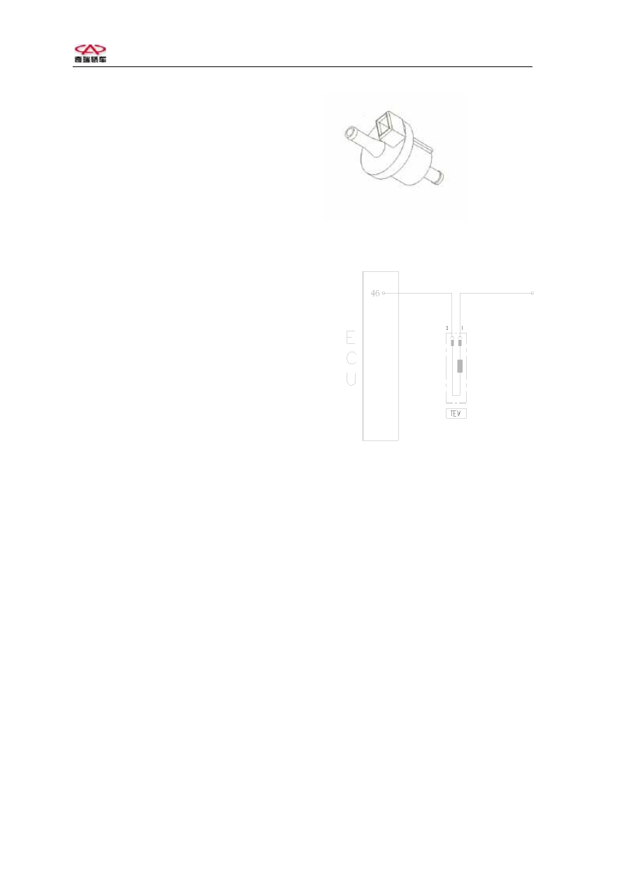
Carbon canister control valve
Main relay
Carbon canister
control valve
Circuit diagram of carbon canister control valve
TEV-2
Pins:
Pin 1 connecting with Pin 87 of output
terminal of main relay;
Pin 2 connecting with Pin 46 of ECU.
Troubleshooting: blockage or crack of
carbon canister causes the increase of air
intake.
12