Chery A11. Manual - part 55


  Index      Chery     Chery A11 - service repair manual


Search            copyright infringement  


Content   ..  53  54  55  56   ..


Chery A11. Manual - part 55


The manual of 4HP14 A/T removing & installing                                                                CHERY AUTOMOBILE CO., LTD 

Press differential oil sealing 09 130 into location   

with installing sleeve 5×46 000 299.     


Install shift shaft oil sealing 06 010 with special 

spindle drift 5×46 000 187. 


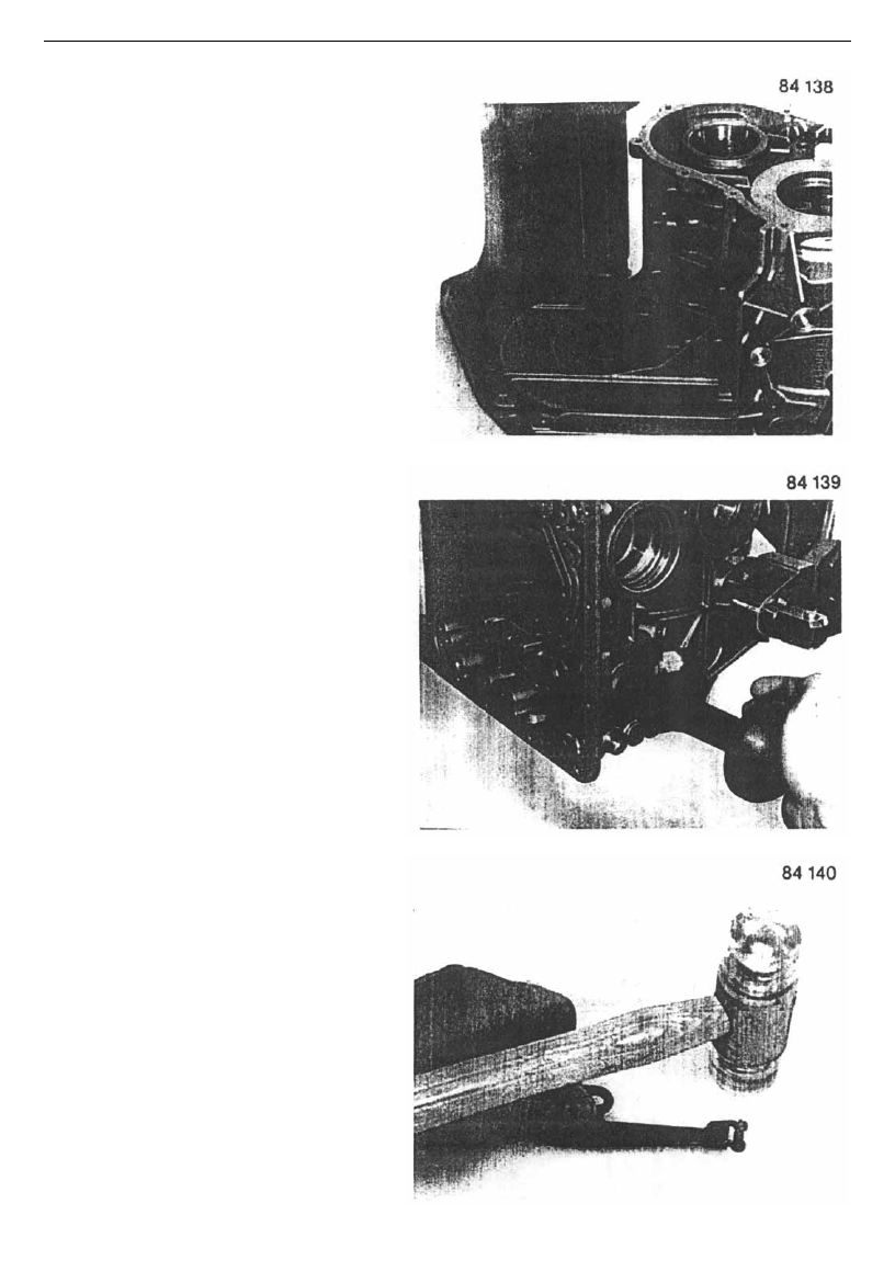
Knock rolling pin 06 030 into pawl spring 06 020 

with a plastic hammer. 


-67-

The manual of 4HP14    A/T removing and installing                                                        CHERY AUTOMOBILE CO., LTD 

Insert brake rotor dowel pin 06 100 and adjusting 

piece 5P 89 001 995.     


Install pawl spring dowel pin 06 040, and then 

install the pawl spring. 


Keep pawl spring close to the adjusting piece, 

and then fix with two bolts 06 050. 

Tool: 27# inner socket spanner 

Torque: 10Nm 


Insert shift shaft 06 060 half or so, then install 

shift cam 06 070 into shift shaft, and assemble 

shift shaft to stop. 


-68- 

The manual of 4HP14 A/T removing & installing                                                                CHERY AUTOMOBILE CO., LTD 

  Connect locking cam 24 020 and brake rotor 06 

110 with the lock spring 24 010. Locking cam 

must be installed on brake rotor. 


Install the whole mechanism on the dowel pin, 

and connect the brake rotor and lock cam with 

spring.   


Shift cam and lock cam MUST BE adjusted to 

installation position. Install brake rotor and adjust 

its location as shown on figure.     


-69-

The manual of 4HP14    A/T removing and installing                                                        CHERY AUTOMOBILE CO., LTD 

NOTE:   

The washer thickness should be adjusted as 

procedures in section 1.4.1 in page 5/1. The 

adjusting washer is installed between the cam 

and the housing. Therefore brake rotor must be 

removed, and pull shift shaft out enough as 

necessary.   


Install shift shaft elastic pin 06 090 with special 

tool 5×46 000 119 and a hammer. 

NOTE: The elastic pin opening side must face to 

transmission input or output direction. 


Insert pawl dowel pin 24 060 half into the house, 

and place retracting spring 24 050 on dowel pin.     


-70- 


Content   ..  53  54  55  56   ..