Loader Bobcat 773. Manual - part 96


  Index      Bobcat     Bobcat 773 - service manual 1997 year


Search            


Content   ..  94  95  96  97   ..


Loader Bobcat 773. Manual - part 96


PISTON AND CONNECTING ROD

Removal And Installation

Remove the cylinder head. (See Page 7–47.)

Remove the top edge from the cylinder bore with a ridge
reamer.

Remove the oil pan.

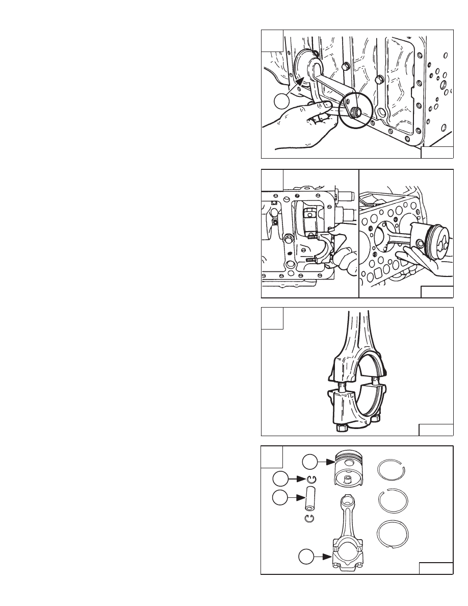
Remove the oil pump strainer (Item 1) [A].

Turn the flywheel and put a pair of connecting rods at
bottom dead center.

Remove the connecting rod bolts.

Installation: Tighten the connecting rod bolts to the
following torque.

W/O Flange Bolt

27–30 ft.–lbs. (37–41 Nm)

. . . . . . . . . 

W/Flange Bolt

33–36 ft.–lbs. (45–49 Nm)

. . . . . . . . . . . 

Remove the rod cap and bearing [B].

Use a hammer handle and push the piston/connecting
rod assembly out of the cylinder bore [B].

NOTE: Make sure the pistons are marked so they will

be returned to the same cylinder bore.

Installation: When inserting the piston into the cylinder,
face the mark on the connecting rod to the injection pump
[C].

Repeat the procedure to remove the other piston/
connecting rod assemblies from the engine block.

Remove the piston rings [D].

Remove the snap ring (Item 3) [D] and piston pin (Item 1)
[D].

Separate the piston (Item 2) [D] from the connecting rod
(Item 4) [D].

A

B–14344

1

C

A–02903

82.8

82.8

D

B–03621

1

3

2

4

773 BICS Loader

–7–63–

Service Manual

B

PI–10013

PISTON AND CONNECTING ROD (Cont’d)

Removal And Installation (Cont’d)

Installation: When installing new rings, assemble the
ring so the mark (Item 1) [A] near the gap faces the top
of the piston. When installing the oil ring, place the
expander joint (Item 2) [A] on the opposite side of the oil
ring gap (Item 3) [A].

Installation: When reassembling, align the marks (Item
1) [B] on the connecting rod and piston (Item 2) [B]. Heat
the piston to 176–212

°

F. (80–100

°

C.) and tap the piston

pin into position. Place the piston rings so that there are
gaps every 120 degrees (Items 3, 4 & 5) [B] with no gap
facing the piston pin in the cylinder.

Servicing The Piston And Connecting Rod

Measure the I.D. of the piston pin bore in both horizontal
and vertical directions [C].

If the measurement exceeds the allowable limit, replace
the piston.

Piston Pin Bore I.D.

0.984–0.985 inch

. . . . . . . . . . . . . . . 

(25,0–25,013 mm)

Allowable Limit

0.986 inch (25,05 mm)

. . . . . . . . . . . . . . 

Measure the O.D. of the piston pin (Item 1) [D].

Measure the I.D. of the connecting rod small end (Item 2)
[D].

Calculate the oil clearance. If the clearance exceeds the
allowable limit, replace the bushing. If it still exceeds the
specifications, replace the piston pin.

Piston Pin O.D.

0.984–0.985 inch (25,0–25,011 mm)

. . 

Bushing I.D.

0.985–0.986 inch (25,03–25,04 mm)

. . . . 

Oil Clearance Between Piston Pin
  & Bushing

0.0006–0.0015 inch (0,014–0,038 mm)

. . . 

Allowable Limit

0.006 inch (0,15 mm)

. . . . . . . . . . . . . . . . 

Service Replacement
  Part

0.0006–0.003 inch (0,015–0,07 mm)

. . . . . . . . . . 

A

PI–10015

180

°

3

2

1

C

A–02733

D

B–03633

1

2

–7–64–

773 BICS Loader

Service Manual

B

PI–10014

5

3

4

2

1

PISTON AND CONNECTING ROD (Cont’d)

Servicing The Piston And Connecting Rod (Cont’d)

To replace the connecting rod small end bushing, make
a driver tool as shown in figure [A].

Use a press and special driver tool to remove the small
end bushing [B].

Installation: Clean the small end bushing and bore. Put
oil on the bushing and press into the connecting rod until
it is flush [B].

Install new piston ring into the lower part of the cylinder
bore. Measure the ring gap with a feeler gauge [C].

If the gap exceeds the allowable limit, replace the cylinder
liner.

Compression Ring Gap

0.012–0.019 inch

. . . . . . . . . . . 

(0,3–0,5 mm)

Oil Ring Gap

0.010–0.016 inch (0,25–0,4 mm)

. . . . . . . . 

Allowable Limit

0.05 inch (1,25 mm)

. . . . . . . . . . . . . . . . . 

Remove the carbon from the ring grooves. Measure the
clearance between the ring and groove with a feeler
gauge [D].

If the clearance exceeds the allowable limit, replace the
piston.

Compression Ring

0.008 inch (0,2 mm)

. . . . . . . . . . . . . . 

Oil Ring

0.006 inch (0,15 mm)

. . . . . . . . . . . . . . . . . . . . . . 

0.984–0.985’’

(25,0–25,011 mm)

A

MC–01366

6.38’’ (162 mm)

1.378’’ (35 mm)

1.098–1.1004’’

(27,9–27,95 mm)

1.063’’ (27 mm)

C

B–03622

D

PI–10017

773 BICS Loader

–7–65–

Service Manual

B

PI–10016

PISTON AND CONNECTING ROD (Cont’d)

Connecting Rod Alignment

NOTE: The small end bushing is the basis of this

check, check the bushing for wear before
doing this check.

Install the piston pin into the connecting rod.

Install the connecting rod on a alignment tool.

Put the gauge over the piston pin and move it against the
face plate.

If the gauge does not fit squarely against the face plate,
measure the space between the gauge and face plate
[A].

If the measurement exceeds the allowable limit, replace
the connecting rod.

Rod Alignment

0.002 inch (0,05 mm)

. . . . . . . . . . . . . . . . 

A

B–04067

–7–66–

773 BICS Loader

Service Manual


Content   ..  94  95  96  97   ..