Loader Bobcat 773. Manual - part 37


  Index      Bobcat     Bobcat 773 - service manual 1997 year


Search            


Content   ..  35  36  37  38   ..


Loader Bobcat 773. Manual - part 37


TILT LOCK VALVE (Cont’d)

Disassembly And Assembly (S/N 509640659 &
Below, S/N 509616541 & Below)

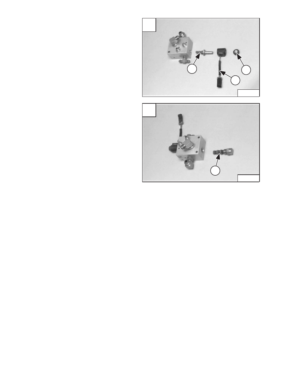
Remove the solenoid mounting nut (Item 1) [A], solenoid
(Item 2) [A] and solenoid valve (Item 3) [A] from the tilt
lock valve.

Remove the check valve (Item 1) [B] from the lift lock
valve.

Assembly: Tighten the solenoid mounting nut to 80–90
in.–lbs. (9–10 Nm) torque.

Inspect the solenoid valve, check valve and hydraulic
fittings for damage or wear. Replace if necessary.

Refer to Page 8–1 for lift arm by–pass control inspection
procedure.

Added Jan. 99

A

P–04115

3

1

2

–2–94–

773 BICS Loader

Service Manual

773 Service Manual #6900092–Hydraulic System Section Part 4 of 4

B

P–04114

1

HYDROSTATIC
SYSTEM

773 BICS Loader

–3–1–

Service Manual

Revised June 01

HYDROSTATIC SYSTEM

CONTROL PANEL

Removal And Installation

3–5

. . . . . . . . . . . . . . . . . . . . . . . . . . . . . . . . . . . . . . . 

Rubber Boot Replacement

3–7

. . . . . . . . . . . . . . . . . . . . . . . . . . . . . . . . . . . . . 

Steering Lever Removal And Installation

3–7

. . . . . . . . . . . . . . . . . . . . . . . . . 

Steering Shaft Disassembly And Assembly

3–6

. . . . . . . . . . . . . . . . . . . . . . . 

Steering Shaft Removal And Installation

3–6

. . . . . . . . . . . . . . . . . . . . . . . . . . 

Steering Shock Removal and Installation

3–6

. . . . . . . . . . . . . . . . . . . . . . . . . 

DRIVE BELT HOUSING

Removal And Installation

3–51

. . . . . . . . . . . . . . . . . . . . . . . . . . . . . . . . . . . . . . . 

FIXED DRIVE BELT TENSIONER PULLEY

Assembly

3–62

. . . . . . . . . . . . . . . . . . . . . . . . . . . . . . . . . . . . . . . . . . . . . . . . . . . . 

Checking Pulley End Play

3–66

. . . . . . . . . . . . . . . . . . . . . . . . . . . . . . . . . . . . . . 

Disassembly

3–60

. . . . . . . . . . . . . . . . . . . . . . . . . . . . . . . . . . . . . . . . . . . . . . . . . . 

Identification

3–59

. . . . . . . . . . . . . . . . . . . . . . . . . . . . . . . . . . . . . . . . . . . . . . . . . . 

Removal And Installation

3–58

. . . . . . . . . . . . . . . . . . . . . . . . . . . . . . . . . . . . . . . 

HYDROSTATIC MOTOR 30 SERIES

Assembly – (S/N 509639899 & Above &
  S/N 509616505 & Above)

3–29

. . . . . . . . . . . . . . . . . . . . . . . . . . . . . . . . . . . . . 

Disassembly – (S/N 509639899 & Above &
  S/N 509616505 & Above)

3–24

. . . . . . . . . . . . . . . . . . . . . . . . . . . . . . . . . . . . . 

Parts Identification – (S/N 509639899 & Above &
  S/N 509616505 & Above)

3–23

. . . . . . . . . . . . . . . . . . . . . . . . . . . . . . . . . . . . . 

HYDROSTATIC DRIVE MOTOR

Disassembly and Assembly – (S/N 509639898 & Below &
  S/N 509616504 & Below)

3–16

. . . . . . . . . . . . . . . . . . . . . . . . . . . . . . . . . . . . . 

Parts Identification – (S/N 509639898 & Below &
  S/N 509616504 & Below)

3–15

. . . . . . . . . . . . . . . . . . . . . . . . . . . . . . . . . . . . . 

Inspection – (S/N 509639898 & Below &
  S/N 509616504 & Below)

3–21

. . . . . . . . . . . . . . . . . . . . . . . . . . . . . . . . . . . . . 

Removal and Installation

3–14

. . . . . . . . . . . . . . . . . . . . . . . . . . . . . . . . . . . . . . . 

Timing the Hydrostatic Motor – (S/N 509639898 & Below &
  S/N 509616504 & Below)

3–22

. . . . . . . . . . . . . . . . . . . . . . . . . . . . . . . . . . . . . 

HYDROSTATIC PUMP

Disassembly And Assembly

3–40

. . . . . . . . . . . . . . . . . . . . . . . . . . . . . . . . . . . . 

Identification

3–38

. . . . . . . . . . . . . . . . . . . . . . . . . . . . . . . . . . . . . . . . . . . . . . . . . . 

Inspection

3–48

. . . . . . . . . . . . . . . . . . . . . . . . . . . . . . . . . . . . . . . . . . . . . . . . . . . . 

Removal And Installation

3–35

. . . . . . . . . . . . . . . . . . . . . . . . . . . . . . . . . . . . . . . 

Swashplate Pre–Load

3–50

. . . . . . . . . . . . . . . . . . . . . . . . . . . . . . . . . . . . . . . . . 

HYDROSTATIC SYSTEM INFORMATION

Checking Charge Pressure

3–4

. . . . . . . . . . . . . . . . . . . . . . . . . . . . . . . . . . . . . 

Replenishing Valve Function

3–4

. . . . . . . . . . . . . . . . . . . . . . . . . . . . . . . . . . . . 

OIL COOLER

Removal And Installation

3–66

. . . . . . . . . . . . . . . . . . . . . . . . . . . . . . . . . . . . . . . 

Page

Number

Continued On Next Page

–3–2–

773 BICS Loader

Service Manual

HYDROSTATIC SYSTEM

SPRING LOADED DRIVE BELT TENSIONER PULLEY

Assembly

3–56

. . . . . . . . . . . . . . . . . . . . . . . . . . . . . . . . . . . . . . . . . . . . . . . . . . . . 

Disassembly

3–55

. . . . . . . . . . . . . . . . . . . . . . . . . . . . . . . . . . . . . . . . . . . . . . . . . . 

Identification

3–54

. . . . . . . . . . . . . . . . . . . . . . . . . . . . . . . . . . . . . . . . . . . . . . . . . . 

Removal And Installation

3–53

. . . . . . . . . . . . . . . . . . . . . . . . . . . . . . . . . . . . . . . 

STEERING LINKAGE

Removal And Installation

3–8

. . . . . . . . . . . . . . . . . . . . . . . . . . . . . . . . . . . . . . . 

Steering Linkage Adjustment

3–10

. . . . . . . . . . . . . . . . . . . . . . . . . . . . . . . . . . . 

Steering Neutral Adjustment

3–12

. . . . . . . . . . . . . . . . . . . . . . . . . . . . . . . . . . . . 

TROUBLESHOOTING

Chart

3–3

. . . . . . . . . . . . . . . . . . . . . . . . . . . . . . . . . . . . . . . . . . . . . . . . . . . . . . . . 

TIGHTEN ALL HARDWARE PER SIZE TO GRADE 5 TORQUE (SEE
STANDARD TORQUE SPECIFICATIONS FOR BOLTS, SECTION 9)
UNLESS OTHERWISE SPECIFIED.

Page

Number

TROUBLESHOOTING

Chart

The following troubleshooting chart is provided for
assistance in locating and correcting problems which are
most common. Many of the recommended procedures
must be done by authorized Bobcat Service Personnel
only.

W–2004–1285

Check for correct function after adjustments,
repairs or service. Failure to make correct
repairs or adjustments can cause injury or
death.

  1.

The hydrostatic pump replenishing valves not seating.

  2.

The steering linkage needs adjustment.

  3.

The hydrostatic pump has damage.

  4.

The final drive chains are broken.

  5.

The hydrostatic motor has damage.

  6.

The tires do not have the correct tire pressure.

  7.

The tires are not the same size.

  8.

The hydrostatic fluid is not at the correct level.

  9.

The oil cooler has a restriction.

10.

The temperature sending switch is not operating correctly.

11.

The loader is not being operated at the correct RPM.

12.

The hydraulic charge pressure sender is defective.

13.

Pump is defective or worn hydrostatics.

PROBLEM

CAUSE

No drive on one side, in one direction.

1, 2

No drive on one side in both directions.

2, 3, 4, 5

The loader does not move in a straight line.

2, 3, 5, 6, 7

The hydrostatic system is overheating.

8, 9, 10, 11

Service code HP 2 appears. (Warnings, low charge pressure.)

8, 11, 12, 13

KEY TO CORRECT THE CAUSE

773 BICS Loader

–3–3–

Service Manual


Content   ..  35  36  37  38   ..